Pусский

Hydrostatic Level Measurement: How to Select a Submersible Level Transmitter
From: Issued date 2026.09.29 Back
Level is one of the few process variables where the measurement principle is genuinely simple and still easy to specify wrongly. A submersible level transmitter does exactly one thing: it measures the weight of the liquid column sitting above it, and infers height from that. The physics does not go wrong. The specification does — through the wrong pressure reference, a range quoted in metres of water for a liquid that is not water, or a vented cable that quietly fills with condensation after the first cold night.
This guide covers hydrostatic level measurement from the principle through to a complete specification, for water and wastewater engineers, tank farm operators, and the system integrators who wire it all together.
Note: this article is about level duty specifically. For a general transmitter selection framework — pressure type, range, accuracy, output, connection, materials, environment, hazardous area — see How to Choose a Pressure Transmitter: A Complete Selection Guide.
What Hydrostatic Level Measurement Actually Measures
A liquid column of height h and density ρ exerts a pressure at its base:
P = ρ × g × h
A sensor immersed at the bottom of that column therefore sees a pressure proportional to the height of liquid above it. Rearranged, the instrument’s job is:
h = P / (ρ × g)
Three consequences follow directly, and every selection decision below traces back to one of them:
The instrument measures the column above the sensor, not the depth of the vessel. Where you mount the sensor becomes part of the measurement. Mount it 300 mm above the tank floor and the bottom 300 mm becomes invisible — by design, not by fault.
The reading depends on density. A range expressed in metres of water column (mH₂O) assumes ρ = 1,000 kg/m³. Any other liquid needs a correction, and a neglected density correction produces a level reading that is consistently wrong by a fixed percentage.
The sensor measures total pressure, which includes the atmosphere. In an open tank, that atmospheric component must be cancelled out — which is what the reference decision below is about.
For reference: 1 mH₂O = 9.81 kPa, and 1 bar ≈ 10.2 mH₂O.
The Seven Decisions at a Glance
| # | Decision | The question you are answering | Get it wrong and… |
|---|---|---|---|
| 1 | Pressure reference | Vented (gauge) or sealed gauge? | Reading drifts with the weather |
| 2 | Range | What span, and relative to which datum? | You measure the wrong part of the tank |
| 3 | Accuracy | What error in millimetres do you need? | ±20 mm becomes ±100 mm |
| 4 | Transmitter type | Submersible, flanged, clamped, or non-contact? | The instrument cannot be installed or maintained |
| 5 | Cable and surge protection | Vented or sealed cable, and what protects it? | The instrument dies in the first storm |
| 6 | Materials | Diaphragm and seal vs. your medium | Blocked port, or corrosion within months |
| 7 | Ingress protection | IP rating of the complete assembly | Water enters through the cable gland |
1. Pressure Reference: Vented Cable vs. Sealed Gauge
A wrong choice here produces an unexplainable reading, so it is worth being precise about.
A sensor at the bottom of an open tank experiences:
liquid column pressure + atmospheric pressure
To report level, the atmospheric component has to be removed. There are two ways to do it.
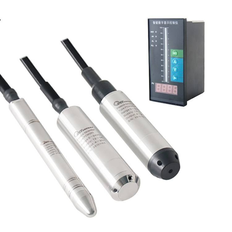
Vented (gauge) reference. The cable contains a small tube open to atmosphere at the dry end, so the reference side of the sensing element sees ambient air pressure. The element then measures gauge pressure — the liquid column only. This is the correct choice for open tanks, sumps, wet wells, reservoirs, boreholes, and open channels.
The vent tube also carries a service risk of its own. If moisture enters it — through a poorly sealed cable end, a breather exposed to rain, or simple condensation cycling — the reference pressure changes and the reading drifts, typically high. Practical protection:
Terminate the vent tube inside a dry junction box, above the high-water line
Fit a desiccant breather on the tube end, and check it periodically
Put a drip loop in the cable below the junction box so water runs off rather than tracking toward the seal
Never cut, kink, or block the vent tube during installation
Sealed gauge reference. The reference side is a sealed, evacuated chamber. This suits applications where a gauge-style reading is wanted but venting is impractical or the atmospheric reference is unreliable — a sealed enclosure, a high-pressure vessel, or an instrument fully potted with no breather path.
Closed and pressurised vessels are a different problem. In a closed tank, the vapour space pressure sits on top of the liquid and the sensor reads both. Neither vented nor sealed gauge solves that. The right answers are a differential pressure transmitter measuring liquid column against vapour space, or a second transmitter measuring the vapour space pressure and doing the subtraction in the control system. A hydrostatic transmitter on a closed vessel without accounting for vapour space pressure will read high by exactly that pressure.
Rule: open vessel → vented (gauge). Closed or pressurised vessel → differential, or subtract vapour space pressure explicitly. Never assume.
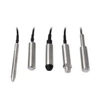
WTsensor’s submersible level transmitters are supplied with vented cable configurations for open-vessel duty; see the level sensor and transmitter range.
2. Range: Size to the Column, and Name Your Datum
Range selection has three components that are frequently conflated.
(a) The physical span you need to measure. Take the maximum liquid height above the sensor mounting point, not the tank’s nominal depth. If the high-level alarm is at 5.5 m and the sensor sits 0.25 m above the floor, the instrument needs to span 5.25 m.
(b) The density correction. Ranges in this product family are expressed in metres of water column. If the medium is not water, convert:
required range (mH₂O) = maximum liquid height (m) × specific gravity
A 10 m column of a liquid with SG 0.85 corresponds to 8.5 mH₂O. Conversely, if you install a 10 mH₂O unit in that liquid, the instrument reaches full scale at about 11.8 m of actual liquid — which may be correct, or may be two metres beyond the top of the tank, wasting two-thirds of the resolution where you actually operate. Confirm which convention you are specifying in, and confirm it in writing.
(c) The submersion requirement, which is not the same as the range. A submersible transmitter’s housing is also submerged to some depth, and that external pressure acts on the enclosure and the cable entry. The instrument’s submersion depth rating and its measurement range are therefore two separate specifications. An instrument ranged 0–5 mH₂O may be installed in a well 12 m deep, where it will be submerged under 12 m of liquid while measuring a 5 m span. Both numbers must be satisfied.
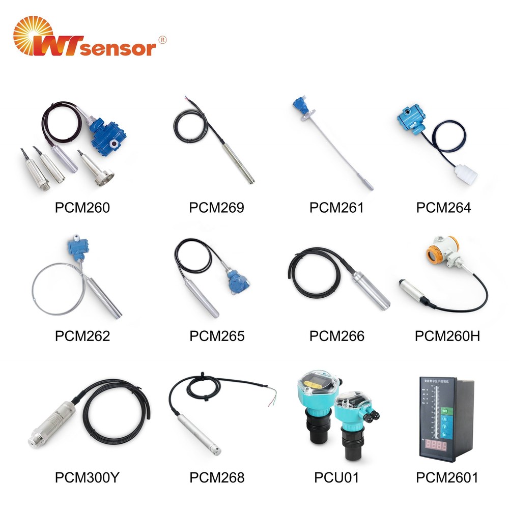
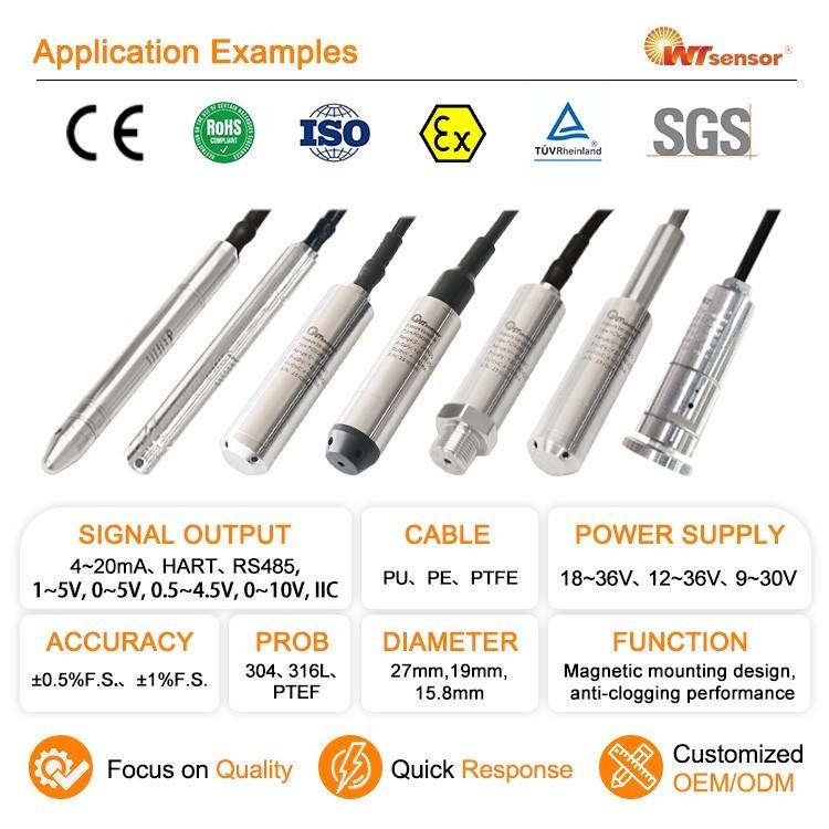
WTsensor’s submersible level transmitters are offered over a 0–1 m to 0–20 mH₂O measuring span in a Φ26.5 mm body (PCM260), with a slim Φ15.8 mm variant (PCM269) for narrow boreholes and small-diameter wells where a standard body will not pass.
On over-range behaviour: a transmitter withstands a proof pressure above its nominal range, defined per model. Exceeding the range does not usually destroy the instrument, but it does mean the output saturates and the level is no longer reported. Size the range to the maximum level you must actually measure, and confirm the proof pressure against the deepest submersion the site can produce.
3. Accuracy: Ask for the Error in Millimetres
Level is unusual among process variables in that a percentage accuracy figure is nearly meaningless on its own. What a control engineer needs is a length.
height error = %FS × measuring span
| Accuracy | 2.5 m span | 6 m span | 15 m span |
|---|---|---|---|
| 0.25 %FS | ±6 mm | ±15 mm | ±38 mm |
| 0.5 %FS | ±13 mm | ±30 mm | ±75 mm |
| 1.0 %FS | ±25 mm | ±60 mm | ±150 mm |
A 0.5 %FS instrument is entirely adequate for pump start/stop control in a wet well, where ±30 mm on a 6 m span changes nothing. The same instrument is unusable for a narrow open channel or a dosing tank where you need ±5 mm. State the required error in millimetres and work backwards to the accuracy class.
Three further points that matter more in level service than in general pressure duty:
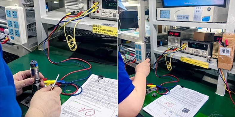
Long-term stability outweighs reference accuracy. A submersible transmitter is usually installed where nobody can reach it — at the bottom of a well, under a manhole cover, in a sump. You cannot re-zero it in place. Thermal effects and long-term drift therefore determine the real performance, not the room-temperature figure.
Temperature affects the medium as well as the instrument. Liquid density falls as temperature rises, so a hot process can shift the density correction. For a liquid whose temperature varies significantly, either compensate for density in the control system or accept the resulting error explicitly.
The mounting position contributes error too. A sensor that is not vertical, or is positioned in a flowing stream rather than still liquid, measures something that is not purely the static column.
4. Transmitter Type: When Contact Beats Non-Contact
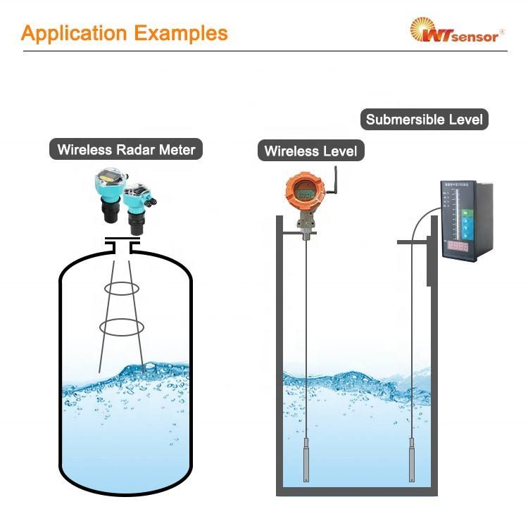
| Type | Best for | Limits |
|---|---|---|
| Submersible (hydrostatic) | Open tanks, sumps, wet wells, reservoirs, boreholes, channels | Requires medium compatibility; needs a whole-instrument IP68 rating; the sensor must be reachable for service |
| Flanged / differential | Closed and pressurised vessels; hygienic, corrosive, or high-temperature media where the sensor must be isolated | Higher cost; impulse lines or capillaries need care |
| Clamped / external | Retrofits where the vessel cannot be opened | Suits only certain tank constructions |
| Ultrasonic (non-contact) | Highly corrosive or hygienic media; no wetted parts | Affected by foam, vapour, condensation on the transducer, temperature stratification, and tank internals |
| Radar (non-contact) | As above, with better tolerance of vapour and foam | Higher cost |
Submersible hydrostatic measurement is often a practical choice for open vessels containing clean to moderately fouling liquids, particularly where continuous contact measurement is acceptable. Its advantage in these duties is mechanical rather than general: a contact instrument is unaffected by foam, vapour, or surface agitation, all of which disturb non-contact methods. Non-contact becomes the practical route when the medium is aggressively corrosive, when hygiene rules out a wetted sensor, or when tank geometry makes access for a submersible instrument impractical. The balance also depends on liquid chemistry, solids content, maintenance access, cable length, and installed cost, so the comparison is best made for the specific installation.
For closed and pressurised vessels, the flanged and differential route is the standard answer; WTsensor’s differential pressure transmitter range and its flanged level instruments cover that duty. For non-contact, ultrasonic level instruments are available alongside.
5. Cable, Termination and Surge Protection
On a submersible transmitter the cable is not an accessory — it is part of the pressure boundary and part of the measurement. Two failure modes dominate field returns, and both are pre-emptable at specification stage.
Moisture in the vent tube (discussed in Decision 1) — protect with a dry termination, a desiccant breather, and a drip loop.
Surge damage. A submersible transmitter is typically at the bottom of a well or sump, connected by a long cable run to a control panel — an excellent antenna for induced surge from nearby lightning. This is a significant failure risk in outdoor water and wastewater installations, and the instrument is often blamed after the fact. Protect the loop:
Fit a surge protector / lightning arrester at the panel end of the cable
Use shielded twisted-pair cable, with the shield grounded at one end only to avoid circulating currents
Route instrument cable away from power and VSD cables rather than alongside them
Keep the shield continuous through junction boxes
Mechanical care. Do not let the instrument hang from its own cable — the cable entry, not the cable, is the load-bearing component. Support the cable at the well head, and leave a service loop so the instrument can be lifted for cleaning. Never lift the transmitter by the cable.
Termination. Land the cable in a dry, IP-rated junction box located above the highest possible water level, not in the wet well itself.
6. Materials and Media Compatibility
316L stainless steel is the correct default for municipal water and wastewater. Beyond that, the medium decides:
| Medium | Watch for | Practical answer |
|---|---|---|
| Municipal water / wastewater | H₂S, chlorides at elevated temperature | 316L is normally adequate; check chloride level and temperature together |
| Sludge, slurry, rag-laden sewage | Solids and fibrous material blocking the sensing port | Protect the port; mount above the sludge blanket; avoid a fully exposed diaphragm where rags can catch |
| Oils and fuels | Seal material compatibility, not just metal | Confirm the seal elastomer against the specific hydrocarbon |
| Chlorinated or dosing chemicals | Aggressive oxidisers | PTFE-coated diaphragm or a corrosion-resistant alloy; confirm by concentration and temperature |
| Beverage and pharmaceutical | Hygiene and cleanability | Hygienic connection and a flush, crevice-free wetted path — with the exact hygienic certification confirmed for the specific model |
| Seawater / brine | Chlorides | Move to a corrosion-resistant alloy rather than relying on 316L |
Two habits worth adopting: assess concentration and temperature together (a medium that is benign at 20 °C can be aggressive at 70 °C), and include cleaning agents and flush fluids in the compatibility list, not just the process fluid.
7. Ingress Protection: Why IP68 Must Cover the Whole Instrument
For a submersible instrument, the IP rating is a specification worth reading closely — and it is often quoted in a way that proves less than it appears to.
IP68 is a two-part test. The “6” is dust (IP6X); the “8” is water (IPX8). A claim of IP68 should therefore be supported by both tests, and the water test must state its conditions: depth or equivalent pressure, and duration. A depth figure quoted with no duration, or a rating that describes only the sensing probe, does not evidence an IP68 instrument.
The failure path is usually the cable entry, not the sensor body. For that reason, the test sample must be the complete assembled instrument — body, seal, cable gland, and cable. An elegantly sealed probe on a poorly glanded cable still floods.
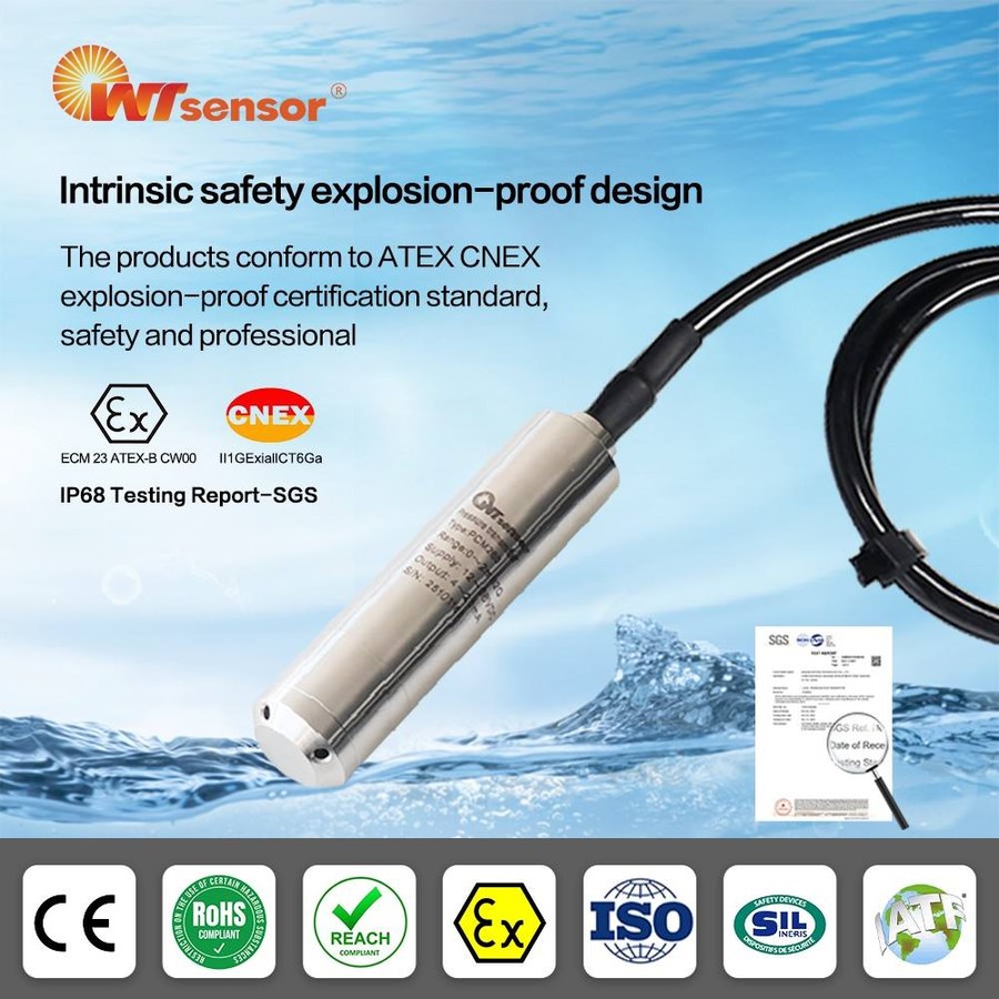
As a concrete reference point for what adequate evidence looks like: WTsensor’s submersible level transmitters PCM260, PCM266 and PCM269 are covered by SGS test reports recording both IP6X (no dust ingress) and IPX8 (no water ingress) on finished-production samples, with the PCM260 unit tested to a 60 m equivalent depth for 48 hours. Equivalently, ask any supplier for the report — not the catalogue line.
This test condition is specific to the sample and method described. It should not be interpreted as a universal IP68 requirement, nor as the transmitter’s measurement range.
Finally, match the junction box environment separately. Housings on outdoor well heads see direct sun, frost, and hose-down; the instrument’s own IP68 says nothing about the enclosure it terminates in.
Submersible Level Sensor vs. Level Transmitter
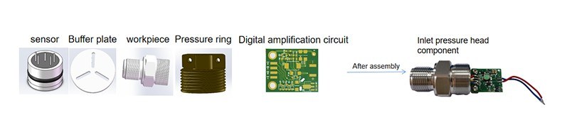
The two terms are used interchangeably in product search, but they describe different levels of integration — and in level duty there is a catch that does not exist in general pressure measurement.
| Submersible level sensor | Submersible level transmitter | |
|---|---|---|
| What it is | Either a bare sensing element with mV-level output, or — loosely — a complete instrument | A complete instrument: sensing element, signal conditioning, compensation, electronics, and a standardised output |
| Output | mV-level; requires external conditioning | 4–20 mA, HART, RS485/Modbus, or wireless |
| Atmospheric reference | Not solved by the element alone — the vent path lives in the cable assembly | Integrated: vented or sealed-gauge reference, terminated and sealed as one assembly |
| Housing and cable | None, or partial | Sealed body, cable entry and cable, rated as one assembly |
| Typical buyer | OEM / instrument manufacturer | Plant, contractor, system integrator |
| Installed | Inside your own instrument | Directly in the vessel |
The level-specific catch: a hydrostatic measurement in an open vessel only reports level correctly if the atmospheric component is cancelled. That cancellation is achieved by the vented cable and its termination — not by the sensing element. Buying a bare submersible sensing element therefore does not by itself give you a working level instrument; you must also provide the vent path, the sealing, and the pressure boundary. That is the main reason a submersible level transmitter is usually purchased as a complete assembly rather than built from a core.
If you are building your own instrument and need the element itself — pressure reference, diameter, output, electrical connection, and material options — see (core selection guide, publishing shortly).
Where Are Submersible Level Transmitters Used?
Submersible instruments suit any open vessel where a sensor can be lowered into the liquid — which covers a wider range of duties than the name suggests. Twelve common ones:
Water wells — the standard duty. Confirm the casing diameter first, then the range.
Boreholes — diameter is the binding constraint; specify the smallest body that passes, and check that the cable and connector also pass.
Reservoirs — long cable runs and exposed locations make surge protection and cable support the main engineering concerns.
River level monitoring — open channel measurement; allow for debris and ice, and protect the cable route against bank movement.
Wastewater wet wells — foam, rag and grease are present; mount above the sludge blanket so the port stays clear. See the water treatment industry applications.
Sumps — small vessels where body diameter and depth together set the range, and cleaning access is usually the deciding factor.
Irrigation systems — distributed, often remote points where the installed cost of cabling frequently favours a wireless level instrument.
Water tanks — open tanks use a vented reference; a closed or pressurised tank needs differential measurement or vapour-space compensation.
Oil and fuel tanks — seal and diaphragm compatibility must be confirmed against the specific hydrocarbon, and the area is usually classified, so the hazardous-area rating applies before any other parameter.
Groundwater monitoring — narrow boreholes again, plus a check on whether the well is artesian or otherwise pressurised, which changes the pressure reference requirement.
Pump stations — the usual requirement is pump start/stop control; size the range to the control band rather than the full well depth.
Mining water monitoring — abrasive, solids-laden water; port protection and the ability to lift the instrument for cleaning matter more than accuracy class.
In each case the seven decisions above still apply — the application only tells you which of them will bind first.
Worked Specification
A municipal wet well for a two-pump sewage station, 6 m deep, with the instrument mounted near the floor and the cable landing in a kiosk above ground:
| Decision | Choice | Reasoning |
|---|---|---|
| Pressure reference | Vented (gauge), vented cable | Open vessel; atmospheric component must be cancelled. Vent tube terminated in the dry kiosk with a desiccant breather and a drip loop |
| Range | 0–6 mH₂O | Well depth 6 m; sensor mounted 0.25 m above the floor, so the measured span is 5.75 m. 0–6 m gives margin without wasting resolution |
| Accuracy | 0.5 %FS → ±30 mm | Adequate for pump start/stop control; a tighter class would not change the control outcome |
| Transmitter type | Submersible, IP68 whole-instrument | Direct contact, no maintenance access required in normal operation; unaffected by the foam and surface agitation a wet well produces |
| Materials | 316L, port protected against rag and solids | Municipal sewage; standard alloy is adequate, but the port must not be allowed to block |
| Cable | Shielded twisted pair, surge protector at the panel, shield grounded one end only | Outdoor well head with a long run — surge is a significant failure risk on long outdoor cable runs |
| Output | 4–20 mA, 2-wire | Existing pump controller analogue input |
| Ingress protection | IP68 assembly; kiosk enclosure matched separately | The assembly rating is what protects the instrument, not the enclosure |
| Hazardous area | Check the kiosk and well head classification | Wet wells can be classified for methane; confirm before ordering |
Note what the specification does not include: a claim that the instrument measures the whole well. The bottom 250 mm is deliberately outside the measurement, because mounting the sensor on the floor of a sewage wet well means burying it in sludge.
Common Selection Mistakes
Using a sealed-gauge instrument in an open well. The reading tracks barometric pressure and drifts with the weather; nobody suspects the instrument because it is “new”.
Moisture in the vent tube. Produces a slow, consistent, high offset — and gets misdiagnosed as instrument drift.
Specifying a range in mH₂O for a liquid that is not water. Introduces a fixed percentage error that survives every calibration.
Forgetting the mounting datum. The sensor cannot measure the liquid below it, and that is a design decision, not a fault.
No surge protection on a long outdoor run. The instrument is blamed for a lightning event it never had a chance to survive.
Reading “IP68” as applying to the probe. The gland is the leak path; the whole assembly must be rated.
Over-sizing the range “to be safe”. Resolution and accuracy are both expressed against full scale — unused range is unused accuracy.
Ignoring vapour space pressure on a closed tank. Reading is high by exactly the vapour pressure, always.
What to Send a Manufacturer: RFQ Checklist
Supplying these in one pass usually removes the need for a round of clarification before a quotation:
| # | Item | Example |
|---|---|---|
| 1 | Vessel type | Open wet well / closed tank / borehole / channel |
| 2 | Vessel depth and geometry | 6 m deep, 2.2 m diameter |
| 3 | Maximum and minimum level to be measured | 5.75 m / 0.4 m |
| 4 | Sensor mounting datum | 0.25 m above floor, on a bracket |
| 5 | Medium and specific gravity | Municipal sewage, SG ≈ 1.0 |
| 6 | Medium temperature | 5–35 °C |
| 7 | Required accuracy in mm | ±30 mm |
| 8 | Output and control system | 4–20 mA, 2-wire, existing pump controller |
| 9 | Cable length and type | 15 m, vented, shielded |
| 10 | Ingress protection | IP68, whole assembly |
| 11 | Hazardous area classification | None / Ex ia IIC T6 Ga |
| 12 | Surge exposure and protection | Outdoor well head, long run — surge protector required |
| 13 | Body diameter constraint | Must pass a 50 mm bore / 2 inch riser |
| 14 | Quantity, certification needs | 8 pcs; material or hygienic certificates as applicable |
With these, a manufacturer can usually confirm the suitable configuration and return a quotation in one round.
About WTsensor
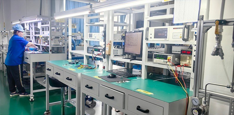
WTsensor (Nanjing Wotian Technology) has manufactured pressure sensors and transmitters since 2005, producing more than 4.5 million pressure sensors a year from a 25,000 m² base with 70+ R&D engineers, and exporting to more than 100 countries. Its level instruments are built on the same in-house diffused silicon and glass micro-fused sensing platforms used across the pressure range, and include submersible, flanged, clamped and wireless variants.
The submersible range covers measuring spans from 0–1 m to 0–20 mH₂O, in standard and slim body diameters, with IP68 ratings evidenced by SGS test reports on finished assemblies. Quality systems are certified to ISO 9001 and IATF 16949, and the range is covered by CE, RoHS, REACH and EMC documentation, with ATEX certification available for hazardous-area duty. Because ranges, materials and cable configurations are built to order, final specifications are confirmed against the current datasheet at quotation.
FAQ
What is hydrostatic level measurement?
It infers liquid level from the pressure a liquid column exerts at the bottom of a vessel, using h = P / (ρ × g). A sensor immersed at the base measures the pressure of the column above it, from which height is calculated. It requires a known liquid density and a known sensor mounting position.
Should I use a vented cable or a sealed-gauge transmitter — and why does my reading drift with the weather?
Vented cable for open vessels — tanks, sumps, wells, channels — because the vent lets the sensor reference local atmospheric pressure so only the liquid column is measured. If an open-vessel reading drifts with the weather, either the instrument is referenced to a sealed chamber rather than to atmosphere, or the vent tube is blocked, kinked, or holding condensation. Sealed gauge suits installations where venting is impractical or an atmospheric reference is unreliable. For closed or pressurised vessels, neither is sufficient: use differential measurement or subtract vapour space pressure explicitly.
How do I select the range for a liquid that is not water?
Multiply the maximum liquid height in metres by the liquid’s specific gravity to get the required range in mH₂O. A 10 m column of a liquid with SG 0.85 needs 8.5 mH₂O of range. Confirm with the supplier which convention the quoted range uses.
Where should the sensor be mounted?
As low as practical, but above any sludge or sediment blanket you do not want to measure through — typically 200–300 mm above the floor in a sewage wet well. Remember that the instrument measures only the column above the sensor, so whatever lies below the mounting point is outside the measurement by design.
Is IP68 enough for a submersible transmitter?
Only if it applies to the complete assembled instrument. IP68 combines a dust test (IP6X) and a water test (IPX8); the water test must state depth or equivalent pressure and duration, and the sample must include the cable gland and cable, because that is where water normally enters. A rating that describes only the probe does not evidence an IP68 assembly.
Why do submersible transmitters fail after storms?
Induced surge on long cable runs at outdoor well heads is a significant failure risk. Protect the loop with a surge arrester at the panel, use shielded twisted-pair with the shield grounded at one end only, and route instrument cable away from power and VSD cables.
Can I use a standard pressure transmitter for level?
For an open tank with a stable liquid, a standard transmitter can be ranged for level, and with a suitable reference it will work. For submersible, deep-well, or permanently wet duty, specify a dedicated level transmitter — the housing, cable entry and ingress protection are designed for continuous immersion in a way a standard industrial transmitter is not.
What about a closed or pressurised tank?
The vapour space pressure adds to the liquid column pressure, so a hydrostatic instrument reads high by exactly that amount. Use a differential pressure transmitter referenced to the vapour space, or measure the vapour space separately and subtract it in the control system.
Need help specifying a level instrument? Send your vessel type and depth, the maximum level you must measure, the sensor mounting position, the medium and its specific gravity, and the accuracy you need in millimetres — WTsensor responds with a recommended configuration and a technical evaluation, typically within one business day.