 Pусский

Ultrasonic vs Radar Level Transmitters: How to Choose the Right Technology
From: Issued date 2026.11.05 Back
This guide is about level measurement where nothing touches the medium. If the medium can be touched, a submersible or a differential pressure transmitter is usually cheaper and simpler; the submersible level transmitter selection guide covers that route. Non-contact earns its place when contact is the problem: the medium coats, corrodes, sets, or has to stay clean.
Two technologies do this job at WTsensor, and they are not interchangeable. Ultrasonic sends sound; radar sends microwaves at 80 GHz. Almost every selection mistake in this category comes from treating them as two grades of the same instrument rather than two different physical methods with different failure modes.
The one difference that decides most jobs
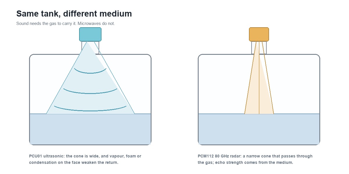
Sound needs something to travel through. Microwaves do not.
That single sentence settles more cases than any specification table. An ultrasonic transducer works by sending a pulse through the air above the liquid and timing the echo. If the space above the liquid is not air — if it is steam, a solvent vapour, a vacuum, or a heavy dust load — the sound either does not get through or gets there too weakened to return. Radar does not care about the gas. It cares about whether the surface reflects microwaves, which is a property of the medium, not of the atmosphere.
The consequence is worth stating plainly, because it runs against the usual instinct that radar is simply the better instrument: radar costs more and solves a different set of problems. On a clean water tank at ambient temperature, an ultrasonic instrument does the job for less money. The money buys capability you may not need.
Decision 1: what is in the space above the surface
Start here rather than with the medium, because the headspace narrows the choice before any other question matters.
| What is above the liquid | Ultrasonic | Radar |
|---|---|---|
| Clean air, indoor or sheltered | Works well | Works, more capability than needed |
| Steam or heavy vapour | Attenuates the pulse; readings drop out | Largely unaffected |
| Foam on the surface | Foam absorbs the pulse; the echo can vanish | Reflects from the foam surface — that is the top of the foam, not necessarily the liquid below it |
| Heavy dust, as in a silo or ash hopper | Scattering weakens the return | Handles dust better at 80 GHz |
| Condensation on the transducer face | A known cause of a reading that freezes or drifts | Condensation forms on the lens too, but a droplet blocks far less of a microwave path than of a sound path |
| Vacuum or near-vacuum | No medium to carry sound | Works |
| Flammable atmosphere | Depends on the certified version | Depends on the certified version; the PCM112 is published as Ex d IIC T6 Gb and Ex ia IIC T6 Ga |
Two of these are worth dwelling on because they cause repeat call-outs. Foam is not a gradual problem: an ultrasonic instrument can read correctly for months and then lose the echo when the process starts foaming. Condensation is the mirror case — a clean installation that starts drifting after the first cold night, because a film of water now sits between the transducer and the air.
Decision 2: temperature and pressure at the process
Temperature affects the two technologies in different ways, and only one of them is a measurement problem rather than a survival problem.
For ultrasonic, the speed of sound in air rises with temperature. The instrument converts a time of flight into a distance using an assumed speed, so an uncorrected temperature shift becomes a distance error in proportion. That is the reason instruments in this class carry temperature compensation, and the PCU01 lists automatic compensation among its features. Compensation handles the ambient shift; it does not handle a process that puts a temperature gradient between the transducer and the surface.
For radar, the speed of light does not change usefully with temperature, so the measurement itself is temperature-independent. What temperature limits is the hardware: the process temperature rating and the antenna and seal materials. The PCM112 datasheet publishes process temperature as −40 to 200 °C standard, extending to 260–300 °C, and the ordering table turns that into a temperature-resistance grade chosen at order time.
One honest detail on the radar datasheet: the operating temperature is published as −20 to 70 °C, with a note that the instrument works normally between −40 and −20 °C but the screen displays abnormally. That is a real limitation stated plainly — the measurement continues in cold weather, the display may not.
Pressure is the faster eliminator. An ultrasonic transducer is a diaphragm that radiates sound, and it needs a pressure it can breathe against. The radar antenna sits behind a lens or a flange and is rated for the vessel: the PCM112 is published for a nominal pressure of −0.1 to 2.5 MPa, which covers most atmospheric and low-pressure tanks but not a pressurised process vessel.
Decision 3: the tank decides as much as the liquid
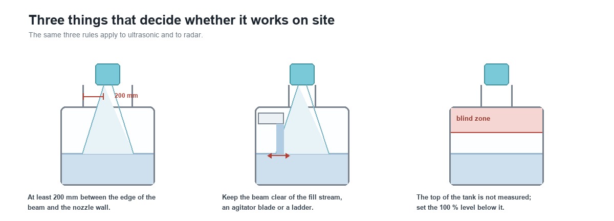
A non-contact instrument measures a path through empty space. Anything that crosses that path is part of the measurement.
Beam angle and what it catches
The beam leaves the antenna as a cone. Its width at the surface grows with distance, so the further the instrument sits from the liquid, the larger the circle it interrogates. Ultrasonic instruments in this range are typically quoted at 8 to 10 degrees; the PCM112 is published at 8, 6 or 3 degrees depending on which of its three lens antennas is fitted.
A narrow beam is not automatically better. It is better where the tank contains structures — an agitator, a heating coil, a ladder, a weld seam, a filling stream — because a narrow cone is less likely to catch them. It is worse where the surface is agitated or the tank is small, because a narrow beam needs a flatter surface to return a clean echo.
Nozzles and standpipes
Both technologies dislike a long, narrow nozzle. The instrument should see the surface, not the inside wall of a pipe. Where a standpipe is unavoidable, its diameter has to be large enough that the beam does not touch the wall before it reaches the liquid — and a stilling well, which is normal practice for a submersible instrument, becomes a liability here.
Blind zone
Every non-contact instrument has a minimum distance below which it cannot measure, because the transducer is still ringing when the echo returns. The PCU01 datasheet publishes a dead zone of 0.4 m or less. The practical consequence is that the top 0.4 m of a tank is not measured, and the 100 % level has to be set below it. Buyers who specify a range equal to the tank height usually discover this at commissioning.
Decision 4: does the medium return an echo
This is the question that separates radar from radar, and it is the one an enquiry tends to skip.
Radar needs a reflection, and the strength of that reflection depends on the dielectric constant of the medium. Water reflects strongly. Hydrocarbons reflect weakly. Some solvents and liquefied gases reflect so weakly that a non-contact radar sees little or nothing, and the answer is a guided radar or a contact instrument rather than a bigger antenna.
Ultrasonic has the mirror-image limitation from the other direction: it reflects from any change in acoustic impedance, so it works on water, slurries, granules and powders alike — which is why ultrasonic instruments are common on solids — but a soft, fluffy material that absorbs sound gives a poor return.
The practical rule: if the medium is a light hydrocarbon or a low-dielectric solvent, do not assume radar solves it. Ask for the dielectric constant before the model is chosen, not after the instrument is installed.
Decision 5: range, antenna and the resolution you actually get
Range is quoted as a maximum, and the usable span is smaller than the number on the datasheet: subtract the blind zone at the top and leave margin at the bottom for the lowest level you need to see.
The two reference products show how differently range is specified. The PCU01 is published in discrete spans of 5, 10, 15, 20 and 30 m, with an accuracy of 0.5 %FS and a display resolution of 1 mm or 0.1 %FS, whichever is coarser. The PCM112 is published as a continuous 0.1 to 150 m range, with three lens antennas of 32, 44 and 76 mm and beam angles of 8, 6 and 3 degrees.
Note what the radar datasheet does not publish: a single accuracy figure. It describes the determinants — antenna size, beam angle, frequency — and leaves the achieved accuracy to the application. That is not an omission to be worked around by inventing a number. It reflects the physics: what a radar achieves depends on the dielectric constant of the medium, the distance, and how flat the surface is. If a project needs a guaranteed figure, ask for it against the specific medium and range rather than quoting a headline.
Resolution and accuracy are also not the same promise. A display that resolves to 1 mm is not an instrument that is accurate to 1 mm; the accuracy line is the one that governs.
Decision 6: output, power and enclosure
This is the least interesting group of questions, and the one that tends to force a second order.
Wiring. Two-wire 4–20 mA is the default in a plant with loop power. Four-wire is what you need when the instrument has to run from mains or when the load is too heavy for a loop. The PCU01 offers both, coded separately at order time; the PCM112 is published in two-, four- and six-wire variants, where the six-wire version exists so that the current output and RS485 can run at the same time.
Digital output. RS485 Modbus is available on the PCU01 as an option and on the PCM112 alongside HART. If the reading is going to a PLC or a gateway rather than to a chart recorder, decide this before the order, not during commissioning.
Relays. Ultrasonic instruments in this class commonly carry relay outputs for pump control — the PCU01 offers a version with two alarm relays. If the instrument is expected to start and stop a pump, that is a different product from the one that only reports level.
Enclosure. The PCU01 is published at IP65. The PCM112 offers cast aluminium, stainless steel or plastic housings, which matters where the instrument sits outdoors or in a wash-down area.
Hazardous area. The PCM112 is published as Ex d IIC T6 Gb and Ex ia IIC T6 Ga. As with any hazardous-area purchase, the certificate for the exact configuration is the document that governs, and it is worth asking for rather than assuming a model-level rating applies to every housing.
The four models side by side
WTsensor covers this decision with three ultrasonic models and one radar model. They are listed together because the choice is usually made on the first two rows, and the rest of the table decides the order code.
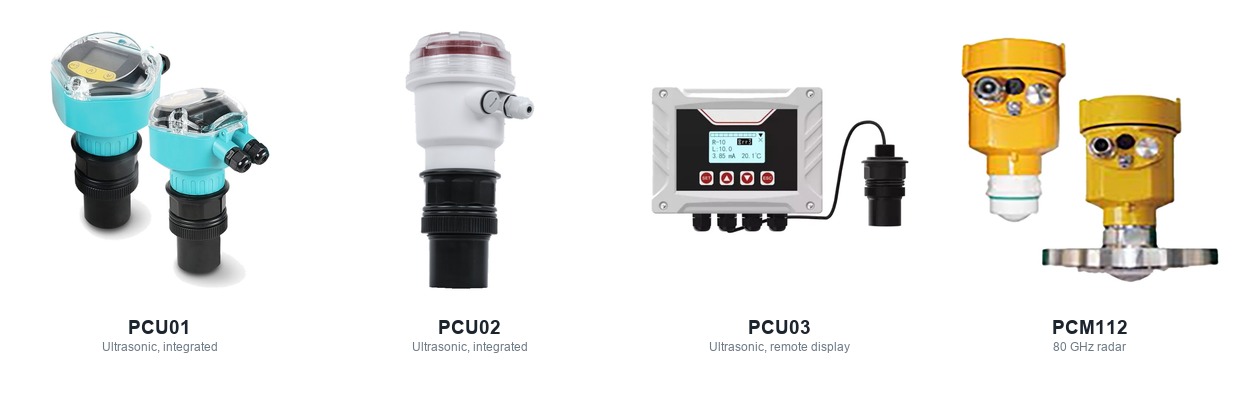
| Model | Principle | Span | Beam | Output | Where it fits |
|---|---|---|---|---|---|
| PCU01 | Ultrasonic, integrated | 5, 10, 15, 20, 30 m | One transducer, no published figure | 4–20 mA 2- or 4-wire; RS485 Modbus optional; alarm relays optional | The general-purpose ultrasonic model. 0.5 %FS, dead zone 0.4 m or less, IP65, −20 to 60 °C, display and keys on the head |
| PCU02 | Ultrasonic, integrated | 5 m, 10 m | One transducer, no published figure | 4–20 mA (load above 500 Ω), RS485, two relays rated 3 A at 250 V AC | For corrosive, viscous or density-variable liquids, where the relay pair can drive a pump without a separate controller |
| PCU03 | Ultrasonic, remote display | 5 m, 10 m | 8° at the 5 m span, 10° at the 10 m span | 4–20 mA | Where the reading has to be at eye level or in a cabinet rather than on the tank: the head is separate and uses touch buttons |
| PCM112 | 80 GHz radar | 0.1 to 150 m | 8°, 6° or 3° by antenna (32, 44, 76 mm) | 4–20 mA 2-, 4- or 6-wire; HART or RS485 Modbus | Vapour, steam, dust, pressure or vacuum. −40 to 200 °C process, −0.1 to 2.5 MPa nominal, Ex d IIC T6 Gb / Ex ia IIC T6 Ga |
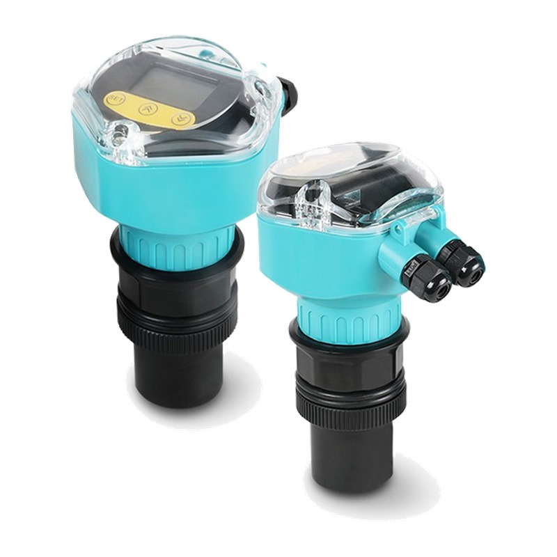 PCU01 General purpose, 5 to 30 m spans, 0.5 %FS | 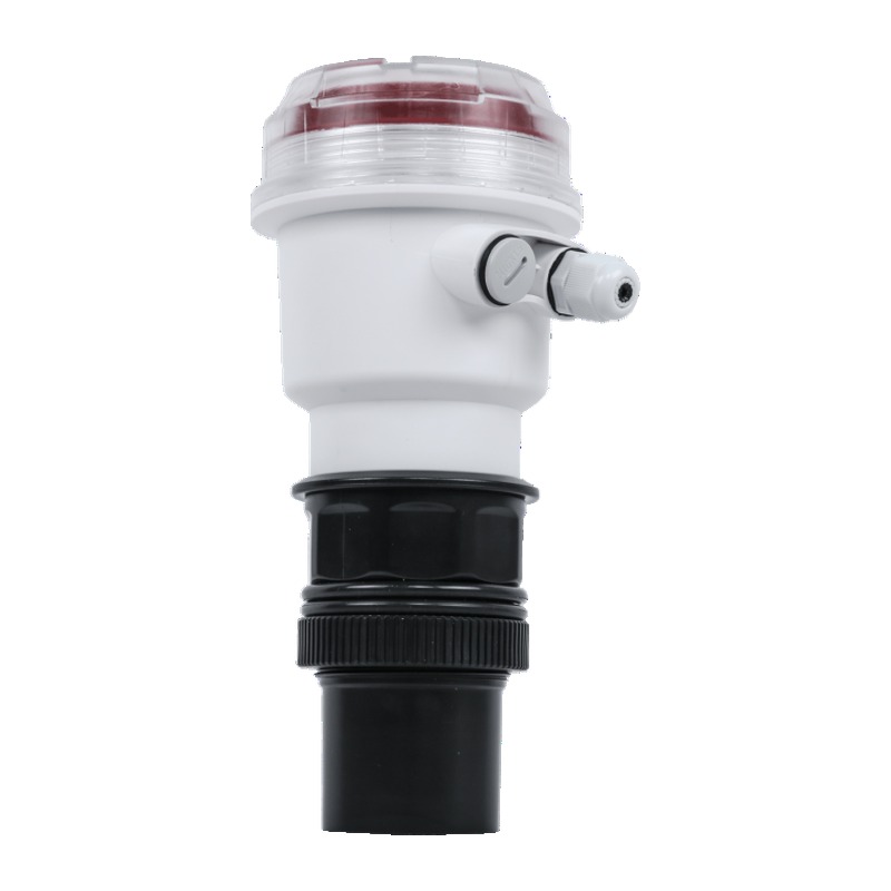 PCU02 Two relays for pump control, corrosive and viscous media |
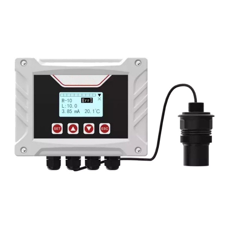 PCU03 Remote display, head separate from the sensor | 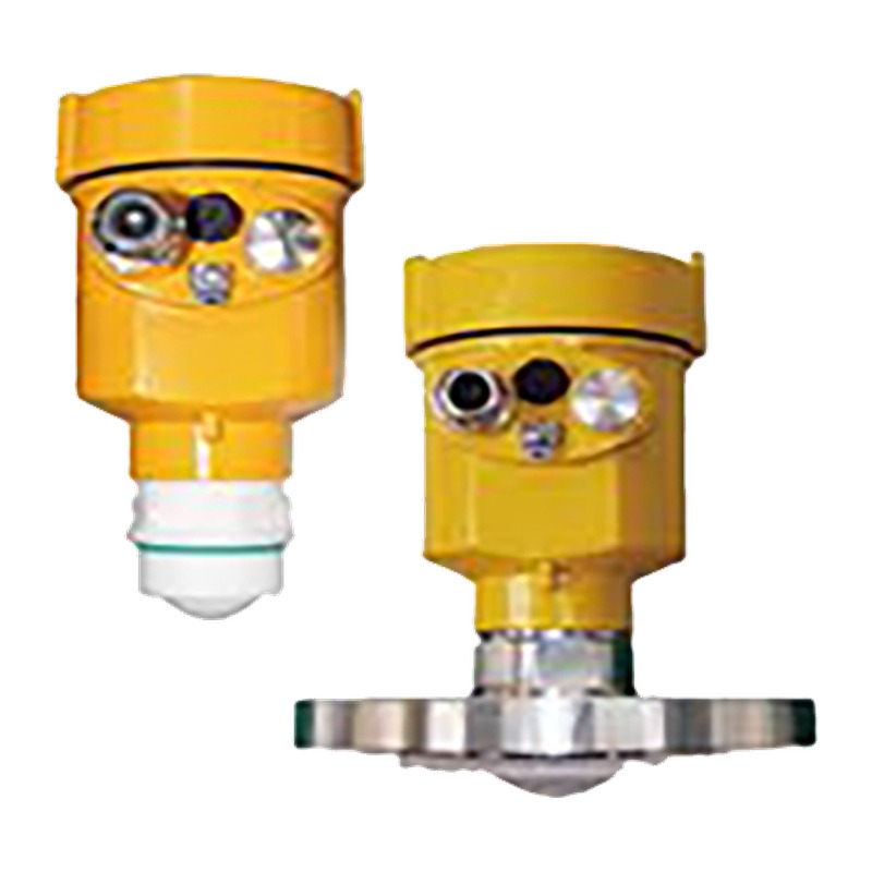 PCM112 80 GHz radar for vapour, dust, pressure and vacuum |
Two notes on the table. The radar datasheet does not publish a single accuracy figure, and that is not an omission to be filled in: what a radar achieves depends on the dielectric constant of the medium, the distance and how flat the surface is. If a project needs a guaranteed number, ask for it against the specific medium and range.
And the beam column shows why the two families behave differently in a tank full of structures. The ultrasonic models use one transducer whose cone widens with distance, so a 30 m span interrogates a wide circle. The radar narrows as the antenna grows: the 76 mm lens gives 3 degrees, which is what makes a tall, narrow silo workable.
Where each one is normally used
| Situation | Normally | Why |
|---|---|---|
| Wet well or sump with pump control | Ultrasonic with relays | Open, atmospheric, condensation handled by the transducer design, relays do the work |
| Water or wastewater channel, open tank | Ultrasonic | Clean headspace, low cost, no need for the radar's capability |
| Chemical tank with vapour above the liquid | Radar | The vapour attenuates sound |
| Solvent or light hydrocarbon storage | Radar, after checking the dielectric constant | Vapour rules out sound; reflection has to be verified for radar |
| Silo with cement, ash, plastic granules | Radar at 80 GHz | Dust scatters sound; the narrow beam avoids the walls |
| Pressurised vessel | Radar is usually the practical option | Provided the pressure rating, the antenna or seal configuration and the temperature limits match the duty. Ultrasonic is workable only where the transducer is rated for the vessel and the acoustic conditions inside it are right |
| Remote or unpowered site | Neither directly; a battery instrument or a wireless transmitter | Both technologies assume a local supply; the wireless measurement route is a different design |
A worked specification
Take a municipal wet well. Six metres from the instrument mounting to the floor, two pumps on alternating duty, hydrogen sulphide in the air, mains power at the rim, and a PLC that reads the level over Modbus. The control room wants the pumps started and stopped by the instrument itself, not by the PLC.
Working through the six decisions:
Headspace. Open to atmosphere, condensation overnight, occasional foam during a storm inflow. No steam, no solvent vapour, no vacuum. Ultrasonic stays in.
Temperature and pressure. Ambient, atmospheric. Nothing here pushes toward radar.
Tank. A vertical wet well with a grille above it; the mounting point is a bracket at the rim, 6.5 m above the floor. That distance minus a 0.4 m dead zone leaves 6.1 m of usable span, so a 10 m instrument covers it with margin.
Echo. Wastewater returns sound well. No dielectric question to answer.
Range. 10 m span covers the working depth with room for the dead zone. Accuracy of 0.5 %FS is 50 mm on a 10 m span, which is finer than the pump start/stop band needs.
Output and power. Mains at the rim, so a four-wire version. RS485 Modbus to the PLC. Two alarm relays, one per pump.
The order code that follows is PCU01-10M-B04-D2-02.
Decoded against the ordering table: PCU01 model; 10M for the 10 metre span; B for the anti-corrosive probe, which is the right choice in a wet well where sulphide attacks a standard transducer; 04 for the four-wire 4–20 mA output; D2 for RS485; 02 for the two alarm outputs that drive the pumps.
Two fields in that code are easy to get wrong. The probe letter and the output code are written together as one group, so B04 is the anti-corrosive probe with the four-wire output — not a probe code followed by an unrelated number. And D0 is no communication; if the PLC link matters, the field has to read D2.
Two conditions in this example need stating rather than assuming. The first is the foam. Ultrasonic is acceptable here only because the foam is occasional, thin and short-lived, and because a brief loss of reading does not by itself create a hazard: the pumps work on a level band, and the well is sized to ride through a lost signal. If the foam is frequent or thick, or if a lost echo during a storm could let the well overflow, the same application points to radar — and then the question becomes whether the radar is reading the foam top or the liquid beneath it, because a foam blanket several centimetres thick is a different level from the water under it. Where the true liquid level matters, neither non-contact technology reads through foam reliably.
The second is the area classification. Hydrogen sulphide is both toxic and flammable, and a wet well is often classified, but whether this one is classified under the local rules is a question for the site rather than for a datasheet. That answer changes the product: the PCU01 datasheet does not publish an explosion-proof version, while the PCM112 is published as Ex d IIC T6 Gb and Ex ia IIC T6 Ga. Where the area is classified, ask before the order whether a certified configuration of the ultrasonic instrument exists.
A control question belongs in the same conversation: what the relay does when the echo is lost. A relay that holds its last state keeps a pump running; one that drops out stops it. Neither behaviour is right for every site, so the choice has to be made deliberately, and an independent high-level switch is the usual answer where an overflow is unacceptable.
For a solvent tank the same six questions produce a different instrument and a different kind of order. The headspace carries vapour, which ends the ultrasonic route; the medium is a light hydrocarbon, so the dielectric constant has to be confirmed before radar is accepted; the vessel may be rated above atmospheric, which selects a pressure code; and the process temperature selects a temperature-resistance grade. On the PCM112 those are separate fields — temperature grade, nominal pressure, flange material and size, antenna, installation — and the code is assembled against the ordering table rather than inferred from a headline model name.
Six failures that happen on site
The instrument is mounted inside its own blind zone. The top of the tank is not measurable, and the 100 % mark ends up above what the instrument can see. Set the span from the dead zone downward, not from the nozzle face.
The nozzle is too narrow. The beam touches the nozzle wall before it reaches the liquid, and the echo that comes back is the nozzle. A short, wide nozzle is better than a long, narrow one, whatever the drawing says.
Foam arrives later. A commissioning that passed in dry weather fails in the first storm. If the process can foam, plan for radar or accept that the reading will drop out.
The transducer face is wet or coated. Condensation, dust or product build-up sits between the instrument and the surface. A reading that freezes at a plausible value is a classic symptom.
Something crosses the beam. A filling stream, an agitator blade, a ladder or a heating coil returns an echo that is closer than the liquid. It is read as a high level.
A false echo from the tank itself. A weld seam, a bracket or the tank bottom returns a fixed echo. Modern instruments handle this with echo mapping or a blanking distance, but the mapping has to be done on site with the tank empty — not from a desk.
What to put in the enquiry
A non-contact level enquiry that arrives with these twelve points can be quoted once and correctly:
The medium, and its dielectric constant if radar is being considered.
Tank height and the working span, with the 0 % and 100 % levels stated as distances from the mounting face.
What is in the headspace: air, steam, vapour, foam, dust, or vacuum.
Process temperature range, and whether the tank is insulated or heated.
Process pressure, or confirmation that the vessel is atmospheric.
Ambient conditions at the instrument: indoor, outdoor, sun, wash-down, frost.
The mounting: thread size or flange standard, nozzle diameter and nozzle length.
Whether the area is classified, and under which certificate the installation is being designed.
The available supply: loop power, 24 VDC or mains, and how many wires the cable can carry.
Whether relays are needed for pump control.
Whether a local display is required, and in which language.
The accuracy the process actually needs, rather than the accuracy the datasheet offers.
Choosing between the two, in one line
For clean, air-filled, atmospheric tanks, ultrasonic is usually the more economical choice. Radar becomes the better answer when steam, heavy vapour, vacuum, pressure or a closed vessel make the acoustic path unreliable. Sound does travel through gases other than air, so vapour alone does not rule out ultrasound; what rules it out is the attenuation, the temperature gradients and the changing composition that come with it. Radar then has conditions of its own: the medium has to return enough energy, the surface has to be readable, and the antenna has to suit the tank. Confirm those before a model is chosen.
Need a model confirmed against your tank?
Send the medium, the tank height with the 0 % and 100 % levels, what is in the headspace, the process temperature and pressure, the mounting thread or flange, and whether the area is classified. With those, the principle can be settled first and the model second, which is the order that avoids buying capability the tank does not need.
Requirements can be sent through the online message form or by email to dr@wtsensor.com. The same address is in the contact block of every level datasheet, and can be used to request a datasheet or certificate for a specific configuration as well as a quotation.
Where to go next
PCU01 ultrasonic level transmitter — the product page for the ultrasonic model used here, with its own datasheet.
PCM112 80 GHz radar level transmitter — the product page for the radar model, including antenna options.
Submersible level transmitter selection guide — for the contact route, where the medium allows it and the price matters.
What is a wireless pressure sensor? — for sites where there is no power or cable at the tank.
Pressure transmitter troubleshooting — for the signal-side faults that look like instrument faults.
How to select a pressure transmitter — for the pressure measurement that often sits alongside the level one.
Also measuring level? The submersible option
Non-contact is the answer when contact is the problem. Where the tank is open and the medium allows it, a submersible (hydrostatic) transmitter generally costs less than either technology above, and it is not troubled by foam, vapour, dust or a narrow nozzle.
WTsensor builds submersible level transmitters from 304 or 316L with PU, PE or PTFE cable, in 27, 19 and 15.8 mm diameters, with 4–20 mA, HART, RS485 or voltage outputs at ±0.5 %FS or ±1 %FS. The sensing section is sealed, and the magnetic mounting and anti-clogging nose are there for sumps and slurries.
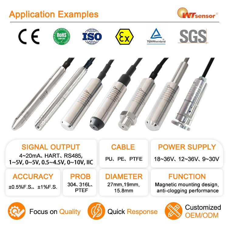
Submersible level transmitter selection guide covers the range, the cable and the installation.
About WTsensor
Nanjing Wotian Technology has been making pressure and level instruments since 2005, and works on three level principles rather than one: submersible (hydrostatic), ultrasonic and radar. That range matters for this particular decision, because the honest answer to "ultrasonic or radar" sometimes involves saying that neither is the right instrument and a submersible transmitter is cheaper — and a supplier who only sells one principle has no reason to say it.
Manufacturing is in Nanjing, with the sensing elements, the assembly and the calibration under one roof. For non-contact instruments, the parts that matter are the transducer or the antenna and the electronics behind them, and both are checked against reference standards before shipment.
Questions that come up in every enquiry
Can an ultrasonic instrument measure through the top of a closed steel tank? No — the pulse has to travel through the headspace, so it needs an opening into the tank, usually a flange or a threaded boss on the roof.
Which one copes with foam? Radar. Foam absorbs the sound pulse, and the ultrasonic reading either drops out or freezes at the last valid value.
Why does my ultrasonic instrument read a level that is too high when the tank is nearly full? The surface has entered the blind zone, which on the PCU01 is 0.4 m or less. The instrument is reporting the nearest surface it can see, which is the transducer face.
Does temperature affect the accuracy? For ultrasonic, the speed of sound rises with temperature, which is why temperature compensation is standard. For radar, the measurement is not affected by temperature; the temperature limits are mechanical, set by the process rating and the materials.
Will radar work on a light oil or a liquefied gas? Only if the surface returns enough energy. Low-dielectric media reflect weakly, and the answer may be a guided radar or a contact instrument rather than a larger antenna. Ask for the dielectric constant first.
What is the narrowest tank radar can handle? The beam angle and the mounting height together decide the footprint. A 3 degree beam on a short standoff keeps the cone small, which is what makes small tanks workable; a wide beam in a small tank sees the walls.
Which one works in a vacuum vessel? Radar. Ultrasonic needs gas to carry the pulse.
Do I need a stilling well? For a non-contact instrument, usually not, and a narrow well can make things worse by confining the beam. Stilling wells belong to the contact technologies.
-
Inside PCM710 Digital Pressure Switch Manufacturing: Assembly & Calibration QC
Read More > -
What is a Glass-to-Metal Seal? Complete Guide for Engineers
Read More > -
What is a Metal Bellows? Complete Guide for Engineers
Read More > -
What is a Wireless Pressure Sensor? Complete Guide for Industrial IoT
Read More > -
How to Choose a Pressure Transmitter: A Complete Selection Guide
Read More > -
Hydrostatic Level Measurement: How to Select a Submersible Level Transmitter
Read More > -
How to Select a Pressure Sensor Core: A Complete Selection Guide
Read More > -
Why a Wrong Pressure Transmitter Reading Is Usually Not a Broken Transmitter
Read More >