 Pусский

Why a Wrong Pressure Transmitter Reading Is Usually Not a Broken Transmitter
From: Issued date 2026.10.15 Back
Why the Fault Is Usually Upstream of the Instrument
A transmitter that reads incorrectly and a transmitter that has failed look identical from the control room. Both show a number that does not match what the process is doing. Separating the two takes a few minutes with a multimeter and a pressure source, and the distinction matters commercially, because one of them is fixed at the instrument and the other is not.
This guide is based on the same failure modes WTsensor engineers encounter when testing and supporting pressure transmitters in industrial installations.
Between the process and the value on the screen sits a chain of five segments:
| # | Segment | What can go wrong there |
|---|---|---|
| 1 | The process | The pressure genuinely changed, or the medium changed state — gas in a liquid line, condensation in a gas line, a slug of solids, a pump behaving differently |
| 2 | Tapping point and impulse line | Blockage, trapped gas or liquid, a partially closed valve, wrong slope, a leaking joint, a frozen line |
| 3 | The transmitter | Zero shift, diaphragm damage, seal failure, water ingress, electronics damage |
| 4 | The electrical loop | Supply out of range, excessive loop resistance, poor termination, moisture in a junction box, interference on an unshielded run |
| 5 | Receiving device and configuration | Range configured differently at the two ends, wrong units, damping set high, a faulty input card or channel |
A fault anywhere in those five segments produces a wrong reading. Only segment 3 is the instrument.
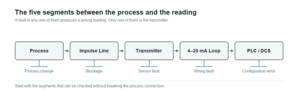
This is why replacing the transmitter first is an expensive way to troubleshoot. If the impulse line is blocked, a new transmitter connected to the same blocked line reads what the old one read, and the fault survives the swap with a new part number attached to it. The cost is not only the part — it is the interrupted process, the rework, and the fact that the real cause is still in place and will produce the same symptom again.
There is a second reason to work through the chain in order. Segments 1, 2, 4 and 5 can be inspected without depressurising the line, and several of them without taking the instrument out of service at all. Segment 3 is the one that requires breaking the process connection. Checking the cheap, non-intrusive possibilities before the intrusive one is not just good practice — it is the difference between a short diagnostic check and a much longer service intervention.

The Order to Work Through a Fault
Three rules keep a fault-finding exercise short.
Confirm the reading is actually wrong before explaining why. Compare the transmitter against something independent: a local gauge on the same tapping, a second instrument, the process history in the control system, or the expected value from how the plant is running. A reading that looks implausible may be correct. Starting from the assumption that the instrument is at fault skips this step, and it is the step that occasionally ends the job with no repair needed.
Isolate one segment at a time. The value of the five-segment split is that each segment can be tested somewhat independently. If a pressurised test at the transmitter produces the expected output, the instrument and the loop are working and the problem is upstream of the process connection. If it does not, the problem is at the instrument, the wiring, or the receiving end. That single test halves the search space, and it can be done in minutes.
Change one thing at a time. A fault-finding session that adjusts the range, re-terminates the wiring and replaces a gasket in one visit leaves the actual cause unknown. If the symptom returns, the whole sequence has to be repeated. Recording what was changed, and what the reading did as a result, is what turns a repair into a diagnosis.
A workable sequence, in the order that usually costs the least:
Confirm the process is doing what you think it is doing.
Check for a blocked or gas-locked impulse line, and check any manifold or isolation valves between the tapping and the instrument.
Verify the loop: supply voltage, loop resistance, terminations, moisture in the junction box.
Verify the receiving end: configured range, units, damping, input channel.
Only then break the process connection and test the instrument itself.
Symptom Quick Reference
Most reported faults fall into one of the following patterns. The pattern points at the segment to check first, which is not the same as the cause — it is where to start looking.
| Symptom | Segment to check first | Typical first check |
|---|---|---|
| No output at all; loop current near zero | Electrical loop | Supply voltage and loop continuity |
| Reading sits at zero or 4 mA regardless of process | Tapping and impulse line | Whether the tapping is open and the line is not gas-locked |
| Reading does not change when the process changes | Tapping and impulse line, or configuration | Whether the manifold is open, and whether the configured range spans the operating point |
| Reading offset by a constant amount, both at zero and at pressure | Transmitter zero, or configuration | Zero with the process connection vented |
| Reading drifts over days or weeks | Transmitter, or installation | Zero repeatability, and whether the drift correlates with temperature or process cycles |
| Reading noisy or fluctuating | Process, or electrical | Whether the fluctuation matches pump or valve cycling, and whether damping is set |
| Reading scaled by a constant factor | Configuration and receiving end | Range and units at both ends of the loop |
| Reading responds slowly to a real change | Tapping and impulse line, or damping | Whether the line is partially blocked, and the configured damping value |
| Reading correct at zero, wrong at pressure | Transmitter span, or mechanical damage | Span verification, and whether the instrument saw an overpressure event |
| Reading changes when the panel or housing is touched | Electrical loop | Terminations, and whether the cable screen is earthed at both ends |
Symptom 1: No Output, or the Loop Current Sits at Its Minimum
The receiving end shows the bottom of the scale, or shows nothing at all.
Check the loop before the instrument. A two-wire transmitter is powered by the same pair that carries its signal, so an interruption anywhere in that pair removes both. Measure the voltage at the transmitter terminals with the loop connected. If it is absent or far below the transmitter's minimum operating voltage, the fault is upstream: a blown fuse, a tripped breaker, a loose terminal, a corroded joint, or a supply that is simply too low for the total loop resistance.
The relationship that governs this is fixed. A two-wire transmitter needs a minimum voltage across its own terminals to operate, and the supply has to be large enough to push 20 mA through the entire loop resistance and still leave that minimum:
maximum loop resistance = (supply voltage − transmitter minimum voltage) ÷ 0.02 A
If a loop works at 4 mA and fails as the current rises, that relationship is the reason, and it is worth calculating rather than assuming. Adding an indicator, a recorder or a longer cable run increases the loop resistance, and a loop that was adequate before a modification may not be afterwards.
If the loop is sound, separate the instrument from the receiving end. Disconnect the transmitter and check whether the receiving channel reads as it does for an open circuit; substitute a loop calibrator or a resistor network and see whether the channel follows. This distinguishes a dead transmitter from a dead input card without needing a replacement of either.
Causes worth checking in this branch
Reverse polarity at the transmitter or at the receiving end. Two-wire instruments are polarity-sensitive, and a re-terminated junction box is enough to introduce this.
Moisture inside the terminal housing or the junction box, bridging terminals or corroding them. This shows up more after rain, washdown or a cold night, which is itself a useful clue.
A supply that is shared with other instruments and is being pulled down by another device on the same circuit.
A transmitter configured for a different supply arrangement than the one it is wired into — for example a voltage-output unit wired into a current loop.
Water ingress through a cable gland or a damaged diaphragm seal, which can take the electronics out as well as the measurement.
If the instrument is a differential transmitter
On a two-port instrument, a minimum-scale reading can also mean the high and low sides are connected the wrong way round, or that one side is blocked while the other is not. Both produce a reading that is stable, plausible in magnitude, and wrong in sign or in magnitude. Confirming which port goes to which tapping, and which tapping is at the higher pressure, is worth doing before suspecting the instrument.
Symptom 2: The Reading Stays Put While the Process Moves
The value is stable, plausible-looking, and does not follow the process. Operators usually notice this before anyone calls it a fault, because the number stops changing at all.
Check the tapping and the impulse line first. A blocked impulse line traps whatever pressure was in it when it blocked, and the transmitter faithfully reports that trapped pressure. The reading looks normal, holds steady, and slowly becomes more wrong as the real process moves away from it. This is one of the more common field findings, and it is invisible from the control room.
What blocks a line depends on the medium:
| Medium | What accumulates | Where it forms |
|---|---|---|
| Slurries and suspensions | Settled solids | Low points, horizontal runs, at the tapping |
| Crystallising or polymerising liquids | Hard deposit | At the tapping and in any cool section of the line |
| Liquids that can freeze | Ice or wax | Exposed runs, unheated sections, after a cold night |
| Dirty gases | Dust and condensate | Low points and dead legs |
| Clean liquids in a gas-filled line | Trapped gas rather than solids | High points — a gas lock, not a blockage |
Gas lock and blockage produce the same symptom by opposite means. A liquid-filled line with trapped gas at a high point transmits less than the true pressure, because part of the line is compressible. A line blocked with solids transmits nothing at all. The remedy differs: a gas lock is cleared by venting at the high point, a blockage by rodding or flushing. Knowing which one is present before opening anything saves a spill.
Check the manifold or isolation valves. A valve left cracked open, or a three-valve manifold with its equalising valve not fully closed, produces a reading that is close to correct but not correct, and stable. On differential instruments the equalising valve produces this symptom, because it short-circuits the two sides.
Check the configured range and damping. A range that does not span the operating point can leave the reading pinned, and a damping value set very high makes a live reading look frozen. Both are configuration faults, not instrument faults, and both are visible in the transmitter's own display or via HART without breaking the process connection.
Symptom 3: The Reading Is Offset by a Fixed Amount
The reading is wrong by the same amount at zero and at operating pressure. The process still moves the reading, and the span looks right.
A constant offset is the signature of a zero problem rather than a span problem, and there are three places it comes from.
Installation. The instrument is mounted above or below the tapping, and the connecting line is filled with liquid. The static head of that column adds to the measured pressure, and it is a fixed addition. On a gas application the same arrangement has little effect; on a liquid application it can be the whole discrepancy. The offset also changes if the liquid in the line changes density — water to oil, for example — which is a useful way to confirm this cause.
Vented versus sealed reference. A gauge instrument needs a path to atmosphere. If the vent path is blocked, filled with water, or was sealed during assembly, the instrument references something other than local atmospheric pressure. The symptom is a stable offset that shifts slightly with weather. On a sealed-gauge or absolute instrument there is no vent, and the corresponding check is that the reference was set correctly at the factory and has not been changed.
Zero shift in the instrument. Zero can move for legitimate physical reasons: overpressure beyond the rated limit, a mechanical shock, thermal cycling outside the compensated range, or a diaphragm that has been deformed. It can also move because someone adjusted it. Where a site has a practice of zeroing instruments on the line, it is worth verifying that the zero was set with the process connection vented rather than at a live process condition.
How to tell installation offset from instrument zero shift. Vent the process connection, or close the manifold and open the vent to atmosphere, so the instrument sees a known reference. A vented gauge instrument should read zero afterwards. If it does, the offset came from the installation. If it does not, the offset is inside the instrument, and the question becomes why it moved.
One caution before zeroing. Adjusting zero at a live process condition removes the offset from the reading without addressing it. If the cause was a static head, the reading becomes correct at that particular process density and wrong at any other. If the cause was a diaphragm that has deformed, the adjustment hides a mechanical failure that will continue to develop.
Symptom 4: The Reading Drifts Over Days or Weeks
The reading was correct at commissioning and has moved gradually. Nobody can point to the moment it changed.
Gradual drift has three recognisable patterns, and the pattern points to the cause.
| Pattern | What it suggests | How to confirm |
|---|---|---|
| Drift tracks ambient temperature — worse in the afternoon, better at night | Temperature effect outside the compensated range, or a compensation problem | Log the reading against ambient temperature for a few days |
| Drift tracks process temperature or production cycles | Thermal cycling, or a medium that changes state in the impulse line | Compare against process history rather than against the clock |
| Drift is monotonic and independent of both | Mechanical change in the element, seal creep, or gradual blockage of the line | Isolate the instrument and check zero repeatability over a week |
Temperature effects are the first thing to rule out, because the compensated range is stated separately from the operating range. An instrument rated to operate across a wide temperature band may only be compensated across a narrower one, and outside that band the reading moves with temperature in a way the datasheet coefficients no longer describe. If the site experiences wider ambient swings than the compensation covers, the drift is not a fault — it is the specification meeting the environment.
Long-term stability is the second consideration. All elements drift, and the datasheet figure that matters is the stability per year, because it compounds over a service interval. An instrument whose accumulated drift over five years exceeds the required accuracy will show exactly this symptom, and the correct response is recalibration at an interval derived from that figure rather than on failure.
Gradual line blockage can imitate drift. A line that is slowly closing builds up a growing error that looks like instrument drift, and it is confirmed by the same test — isolate the instrument, check its zero, and if the zero is sound, look at the line.

Symptom 5: The Reading Is Noisy or Fluctuating
The reading moves faster or further than the process plausibly can. The average may be correct while the instantaneous value is unusable for control.
First establish whether the fluctuation is real. If the process includes a reciprocating pump, a compressor with a pulsation, a fast-acting valve or a two-phase flow, a fluctuating pressure is a real physical signal, and the instrument is reporting it correctly. The check is whether a second instrument on the same tapping, or the same instrument after damping, shows the same pattern. If it does, the answer to the problem is a damping or averaging strategy, not a repair.
If the fluctuation is not in the process, the cause is electrical or mechanical.
| Cause | Signature | Check |
|---|---|---|
| Electromagnetic interference from a nearby drive, contactor or welder | Noise appears when the other equipment runs; disappears when it stops | Correlate with the operating state of nearby equipment |
| Cable screen earthed at both ends | Low-level noise, sometimes with a DC offset | Inspect screen termination — it is intended to be earthed at one end |
| Poor termination or a loose terminal | Erratic, worse when the panel is touched or the ambient temperature changes | Mechanical inspection of every terminal in the loop |
| Moisture or condensation in a junction box | Comes and goes with weather | Open the box after a cold night or after washdown |
| Mechanical vibration transmitted through the mounting | Correlates with machine speed | Compare against vibration state; check mounting rigidity |
| Damping configured to zero where the process has pulsation | Steady-state value correct, instantaneous value unstable | Read the configured damping value |
Damping is a control decision, not just a display setting. Raising the damping smooths the reported value, and it also delays the response to a real change — which is the trade-off, and it is why damping should be set deliberately against the control loop's requirements rather than raised until the display is calm. A loop tuned with heavy damping and no understanding of the delay will behave differently after a setpoint change, and the resulting complaint is usually described as an instrument problem.
Diagnosing noise with a multimeter or a loop calibrator is often more informative than watching the display, because the measuring device has a different bandwidth. If the loop current is steady at the terminals while the receiving channel shows movement, the noise is being introduced downstream of the transmitter.
Symptom 6: The Reading Is Scaled by a Constant Factor
The reading moves with the process and looks plausible, but it is consistently high or consistently low — roughly half, or roughly double, or off by a fixed ratio.
This is a configuration symptom more often than a hardware one, and there are only a few places a scale factor can enter.
The configured range does not match the range the receiving end assumes. A transmitter configured 0–10 bar reporting into a channel scaled 0–16 bar produces a reading that is wrong by a fixed ratio and moves correctly. This is worth checking first because it requires no process intervention.
Units differ between the two ends. bar against psi, kPa against MPa, metres of water column against bar. The factor is not constant-looking to the operator, because the number changes with the process, but it is constant in engineering terms.
The receiving end maps the current to a different engineering range than the one configured in the transmitter. The 4–20 mA signal carries no intrinsic scaling; the meaning is entirely a matter of agreement between the two ends.
On a differential instrument, the reading corresponds to a different pressure definition than expected — for example a reading that is the difference between two ports while the requirement was the absolute or gauge pressure on one of them.
Corroborate with a calculation rather than by adjusting. Take a known process condition, compute the current it should produce from the transmitter's configured range, and compare that with the current actually measured in the loop. If the loop current matches the calculation and the displayed value does not, the transmitter and loop are correct and the receiving end's scaling is wrong. If the loop current itself is wrong, the transmitter's configuration is the place to look. This one comparison separates the two ends without changing either.
A related case is a span that is partially wrong: correct at one point and wrong at another. That is not a scale factor, and it points either at a span configuration error or at mechanical change in the element, which is covered later in this guide.
Symptom 7: The Reading Responds Slowly
The reading eventually reaches the correct value and takes longer than the process demands to get there. Control loops feel this as sluggishness; operators describe it as the instrument being slow.
Slow response has three quite different causes.
Restriction between the process and the element. A partially blocked impulse line, a nearly closed valve, a small-bore fitting, or a long thin line all restrict flow into the measuring element, and the element then responds as fast as the restriction allows. The signature is a reading that is correct in steady state and slow to change during a transition. On a differential instrument, an equalising valve that is not fully closed produces a similar effect.
Configured damping. Damping deliberately delays the reported value. It is the correct answer to a pulsating process and the wrong answer where the reading has to track a real transition. If a site has damping set high for a good reason and the loop now needs faster response, the conflict is between the two requirements and has to be resolved explicitly, not by ignoring one of them.
Volume in the measuring system. A diaphragm seal with a long capillary, or an assembly with a large internal volume, adds a filling-fluid path that has to move before the element sees a change. This is a property of the installation design rather than a fault, and it is why remote-seal assemblies are specified with the response requirement in mind. Where the temperature of the capillary also changes, the filling fluid expands and contracts, which adds a further slow component that is not related to the process at all.
Distinguishing them. If the instrument responds quickly to a pressure applied directly at its port but slowly to a process change, the delay is upstream of the instrument — in the line, the valves or the seal assembly. If it responds slowly even to pressure applied directly at the port, the delay is in the instrument or its configuration. That single comparison is usually enough.
Pressure Transmitter Troubleshooting Checklist
The checklist below can be worked through on site in the order shown, and it can be printed or captured as a screenshot for a maintenance file. With one exception — applying a known pressure at the transmitter port — none of it requires breaking the process connection.
| # | Check | # | Check |
|---|---|---|---|
| 1 | ☐ Confirm the process condition | 11 | ☐ Check zero |
| 8 | ☐ Check loop resistance | 5 | ☐ Measure loop current at the transmitter |
| 2 | ☐ Check the tapping point | 12 | ☐ Apply a known pressure |
| 9 | ☐ Check HART configuration | 6 | ☐ Measure transmitter supply voltage |
| 3 | ☐ Check the impulse line | 13 | ☐ Check span |
| 10 | ☐ Check receiving-end scaling | 7 | ☐ Check for water ingress |
| 4 | ☐ Check the manifold or isolation valves | 14 | ☐ Check surge protection |
The table that follows explains what the less obvious items establish, and what you need in order to run them.
| Check | What it establishes | What you need |
|---|---|---|
| Measure loop current at the transmitter terminals | Whether the instrument is producing the current its reading implies, and therefore whether the fault is at the instrument or downstream | Multimeter in series, or a loop calibrator |
| Measure supply voltage at the transmitter, loop connected | Whether the supply is adequate for the loop resistance at 20 mA | Multimeter |
| Read the configured values over HART | Range, units, damping, zero and span as the instrument actually holds them, rather than as the documentation says | HART communicator or configuration software |
| Compare the configured range at both ends of the loop | Whether a scale-factor error exists between the transmitter and the receiving channel | Access to the control system configuration |
| Correlate the reading with ambient temperature and with process events | Whether the behaviour is thermal, process-driven, or independent of both | Historical data from the control system |
| Inspect terminators, junction boxes and cable screens | Moisture, corrosion, loose connections, screen earthed at both ends | Access and a torch; a meter for continuity |
| Vent the process connection and check zero | Whether a fixed offset comes from the installation or from the instrument | Manifold or bleed valve; a known reference |
| Apply a known pressure at the transmitter port | Whether the instrument and loop track correctly, independent of the installation | Hand pump and a reference gauge |
| Check zero and span, and record the result | Whether the instrument is within specification, and what it was on the day | Hand pump, reference, and a record sheet |
The last item is worth treating as a routine rather than as a fault response. A recorded zero and span at commissioning, and again at each planned outage, turns an argument about whether the instrument has moved into a comparison of two numbers.
When the Instrument Itself Has Failed
Some faults genuinely are in the instrument. They are worth recognising, because each has a characteristic signature and a cause that can be traced.
| Failure mode | What happens | How it presents |
|---|---|---|
| Diaphragm deformed by overpressure | The element is pushed beyond its elastic range and does not return to its original position | Zero shift that persists after venting, with the span often affected as well. A pressure excursion — a valve closing, a line isolated and warmed, a pump start — is usually in the history |
| Corrosion or erosion of the wetted parts | The diaphragm or the seal face is attacked by the medium and loses material | Gradual drift or a step change, with visible pitting, staining or perforation on inspection. The medium and the material have to be reviewed together, because the same material may be adequate at one concentration and temperature and not at another |
| Seal failure and water ingress | Moisture reaches the electronics through a gland, a damaged cable, a corroded housing or a failed diaphragm seal | Erratic output, output that fails after rain or washdown, or a reading that drifts with humidity. Often accompanied by visible corrosion inside the terminal housing |
| Damage from a surge or a lightning transient | The loop electronics are stressed beyond their rating by an induced transient | Output out of range, no output, or an instrument that works until a particular piece of plant operates. Long cable runs and outdoor routing are the usual setting |
| Sensor or compensation circuit failure | The signal path inside the instrument stops behaving within its specification | Non-linearity, a span error with a sound zero, or readings that change when the instrument is warmed or cooled. Confirmed by calibration rather than by inspection |
Two of these deserve a note. Water ingress and surge damage are both installation-sensitive failures: the instrument is at the end of a cable, and what arrives along that cable — moisture or a transient — determines whether it survives. Both are addressed at installation, which is the subject of the next section.
Pressure transmitter water ingress is worth looking at directly, because the route is usually the same. Moisture enters through a gland, a cable entry or a failed diaphragm seal, and once inside it corrodes the terminals before it reaches the measurement. A fault that appears after rain or washdown, and then clears, is worth investigating rather than logging as a glitch.
Pressure transmitter surge protection and lightning protection follow the same logic, and both are specification decisions rather than site fixes. Surge protection is fitted to the loop so that an induced transient — from a switching event, a nearby strike or a piece of plant starting — does not reach the loop electronics. Lightning protection on the building services and surge protection on the instrument loop are separate measures, and the second is the one that protects the transmitter itself.
And overpressure is worth checking against the specification rather than against the operating pressure. What deforms a diaphragm is the peak it saw, not the value it normally reads, and the peaks come from events that are not part of normal operation.
Reducing Field Faults at Installation
Several of the field problems described above are decided long before the instrument is energised. None of them are complicated, and each one is cheaper at installation than at 3 a.m.
| Decision | What it prevents |
|---|---|
| Tapping point on top for gas, on the side for liquid, with the line sloping to drain or to vent | Trapped gas in a liquid line, trapped liquid in a gas line, and the offset and sluggishness that both produce |
| Slope the impulse line continuously, with no low point for liquids to settle in and no high point for gas to collect in | Progressive blockage and gas locking |
| Provide a vent at the high point and a drain at the low point, and make them accessible | Having to break a connection to clear a line, which turns a routine task into a shutdown |
| Keep the impulse line short and of adequate bore | Slow response, and a line that is easy to block |
| Use a diaphragm seal where the medium would block or corrode the element | Blockage at the tapping and corrosion of the wetted parts, and it allows the instrument to be removed without exposing the process |
| Fit surge protection on long or outdoor loops | Transient damage to the loop electronics |
| Earth the cable screen at one end only | Noise, and circulating currents in the screen |
| Seal cable entries properly, and mount the housing so water runs off it rather than into it | Moisture ingress through glands and entries, which is the route by which most water reaches the electronics |
| Record the configured range, units and damping, and the zero and span at commissioning | Configuration disputes later, and arguments about whether the instrument has moved |
The common thread is that the installation determines which faults the instrument will see over its service life. An instrument in a well-sloped, well-vented, surge-protected installation with a correctly sized seal is largely protected from common field failure modes. The same instrument in a poor installation still fails within specification.
What to Carry to Site
| Item | Used for |
|---|---|
| Digital multimeter with a mA range | Loop current, supply voltage, continuity, screen checks |
| Loop calibrator | Substituting a known current to test the receiving channel, and reading the loop without breaking it |
| Hand pressure pump with a reference gauge | Applying a known pressure at the transmitter port |
| HART communicator or configuration software | Reading the configured range, units, damping, zero and span as actually held |
| Adjustable spanner or the correct spanner for the process connection | Removing and refitting the instrument without damaging the connection |
| Thread sealing consumables matched to the connection | Reinstating the process seal correctly |
| A torch and a mirror | Inspecting the tapping, the underside of the housing and the inside of junction boxes |
| A record sheet for the readings taken | Turning the visit into a diagnosis rather than a repair |
Where to Go Next
Fault-finding and selection are two ends of the same problem. If this guide has raised a question about choosing the instrument in the first place, the following pages cover that side.
Selection
How to choose a pressure transmitter — the eight decisions that define an instrument before it is ordered, including the pressure reference, range, accuracy and environment decisions that determine which faults are possible later.
How to select a pressure sensor core — the same decisions at the element level, for OEM integration.
Submersible level transmitter selection guide — for hydrostatic level applications, where vented cable and IP68 are the equivalent decisions.
Instruments
Pressure transmitters — gauge, absolute and sealed-gauge instruments, including configuration options.
Differential pressure transmitters — two-port instruments, where the impulse line and manifold checks in this guide apply most directly.
Level sensors and transmitters — hydrostatic level measurement, where a blocked or vented line produces the same symptoms.
Construction and sealing
Internal structure of a diffused silicon pressure sensor — what is behind the diaphragm, and which of those parts fails in each of the failure modes above.
Glass-to-metal seal manufacturer guide — the hermetic feedthrough that keeps moisture away from the electronics.
Hermetic sealing — sealed connectors and feedthroughs for instrument assemblies.
About WTsensor
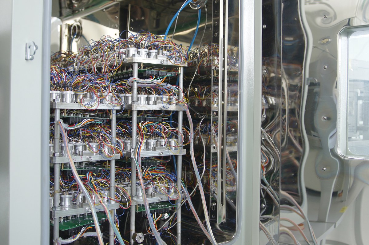
WTsensor (Nanjing Wotian Technology) manufactures pressure transmitters and the sensing elements inside them. Because the element and the instrument come from the same production, the behaviour described in this guide is characterised at the factory rather than assembled from bought-in parts.
Two production stages bear directly on field reliability. Elements are aged before release, so that early-life drift appears at the factory rather than in the field during commissioning. They are then temperature-compensated, which is what sets the compensated range quoted on the datasheet and therefore how the instrument behaves across the ambient swings of a real installation.
For installations where moisture ingress is a concern, instruments are supplied with SS316L wetted parts and potted electronics. Ingress protection is certified by third-party test on the relevant models, and hazardous-area variants carry Ex d IIC T6 Gb or Ex ia IIC T6 Ga certification. WTsensor instruments carry an 18-month warranty, against a market norm of 12.
For site engineers who need to confirm whether an instrument is operating within specification, calibration records and configuration details are available for the specific model at quotation. Final specifications are confirmed against the current datasheet.
FAQ
Should I replace the transmitter first when the reading is wrong?
Not before confirming the reading is wrong and isolating the segment. If the impulse line is blocked or the receiving channel is misconfigured, a replacement instrument will reproduce the fault exactly. The one test that halves the search — applying a known pressure at the transmitter port — takes minutes and requires no replacement part.
How do I tell an instrument zero shift from an installation offset?
Vent the process connection so the instrument sees a known reference. A vented gauge instrument should read zero. If it does, the offset came from the installation — commonly a liquid column in the connecting line, or a blocked vent path. If it does not, the offset is inside the instrument, and the next question is what moved it.
The reading is stable but does not follow the process. What is the first thing to check?
The tapping and the impulse line. A blocked line traps the pressure it held when it blocked, so the transmitter reports a steady, plausible value that quietly becomes more wrong. On differential instruments, also check that the manifold is open and the equalising valve is fully closed.
The reading fluctuates. Is that necessarily an instrument fault?
Not necessarily. If the process includes a reciprocating pump, a fast-acting valve or two-phase flow, the fluctuation is real and the instrument is reporting it. The distinguishing test is whether a second instrument on the same tapping shows the same pattern. Where the fluctuation is not in the process, the usual causes are interference from nearby equipment, a cable screen earthed at both ends, or a loose termination.
How often should a transmitter be recalibrated?
The interval follows from the long-term stability figure on the datasheet, because that drift accumulates over the service interval and determines when the instrument leaves its accuracy band. A transmitter with a tighter stability specification supports a longer interval. Where the instrument is inaccessible or recalibration interrupts production, the stability figure is the more important of the specification numbers, and a recorded zero and span at each outage turns the interval into a decision based on data.
What causes a reading that is correct at zero and wrong at pressure?
Either a span configuration error, or mechanical change in the element after an overpressure event. The configuration possibility is checked without breaking the process connection. If the configuration is correct, the history is worth reviewing for a pressure excursion — a valve closure, an isolated and warmed line, or a pump start — because the element responds to the peak it saw rather than the value it normally reports.
-
How Threaded Pressure Sensor Cores Prevent Leakage Through Controlled Manufacturing
Read More > -
How Welded Pressure Transmitters Prevent Leakage Before Calibration
Read More > -
Why Temperature Transmitters Drift—and How Our Production Process Prevents It
Read More > -
What is a Glass-to-Metal Seal? Complete Guide for Engineers
Read More > -
What is a Metal Bellows? Complete Guide for Engineers
Read More > -
What is a Wireless Pressure Sensor? Complete Guide for Industrial IoT
Read More > -
How to Choose a Pressure Transmitter: A Complete Selection Guide
Read More > -
Hydrostatic Level Measurement: How to Select a Submersible Level Transmitter
Read More > -
How to Select a Pressure Sensor Core: A Complete Selection Guide
Read More >
This article Tags: pressure transmitter troubleshooting field maintenance 4-20mA loop impulse line
Back to List