 Pусский

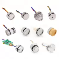
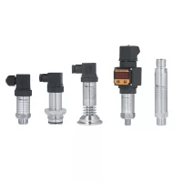
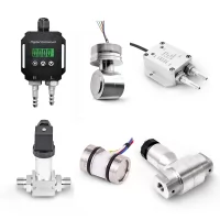
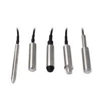
How to Select a Pressure Sensor Core: A Complete Selection Guide
From: Issued date 2026.10.08 Back
What You Are Actually Buying
When you buy a pressure sensor core, you are not buying a finished instrument. You are buying the sensing element and the mechanical boundary around it, and you are agreeing to build everything else yourself: the housing, the signal conditioning, the connector, the calibration, and the documentation that your own customer will eventually ask for.
That is a deliberate trade. A core gives you a high degree of freedom over the finished product, and a corresponding degree of responsibility. You decide what the product looks like, what it is called, and where it is sold. In exchange, every interface the core presents to the outside world becomes your problem to solve, and some of those problems are significantly easier to solve at the specification stage than after tooling exists.
This guide works through the decisions that define a core. For each one it explains what the choice actually changes, what happens downstream if the choice is wrong, and what a sensor manufacturer needs from you in order to quote accurately.
Pressure Sensor Core Types
Selection starts on two axes that are independent of each other: how the element senses pressure, and how it is ported and mounted. They are orthogonal. The same sensing family can be built as a single-port element or as a differential element, and it can be supplied in a threaded body or with a flush diaphragm. Treating them as one flat list of "types" is the first place buyers get confused, so they are separated here.
By sensing family
| Family | Sensing principle | Where it fits |
|---|---|---|
| Diffused silicon | Silicon piezoresistive | The mainstream family for gauge, absolute and sealed-gauge duty across a wide range of industrial and OEM work |
| Monocrystalline silicon | Silicon piezoresistive, single-crystal element | Where reference accuracy and long-term stability need a tighter ceiling than the diffused-silicon family provides |
| Glass micro-fused | Strain gauge, fused to the diaphragm | Rugged and corrosion-resistant duties, and higher-pressure work where a fused element suits the construction |
By port and mounting configuration
| Configuration | What it is | Where it fits |
|---|---|---|
| Single port | One pressure port acting on the element, with a gauge, absolute or sealed-gauge reference | The common case in pressure measurement — see Decision 1 for how the reference is chosen |
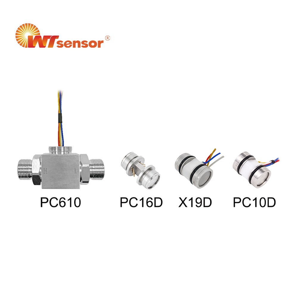
| Two port (differential) | Two pressure ports acting on a shared diaphragm, with the output proportional to the difference | Flow across a restriction and filter or strainer monitoring, where a genuine two-port connection is wanted |
| Threaded body | The element screws directly into a machined port, with the process seal made at the thread or at a face | The common OEM arrangement, and the easiest to integrate into an existing manifold |
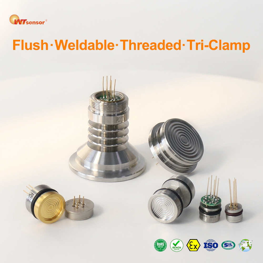
| Flush / flat diaphragm | The wetted face sits level with the mounting surface, leaving no cavity in front of the diaphragm | Viscous, crystallising or particulate-laden media, where a cavity would retain residue |
| Sanitary (Tri-clamp) | A hygienic flush connection with a clamp fitting | Food and pharmaceutical duty, where the joint is cleaned in place |
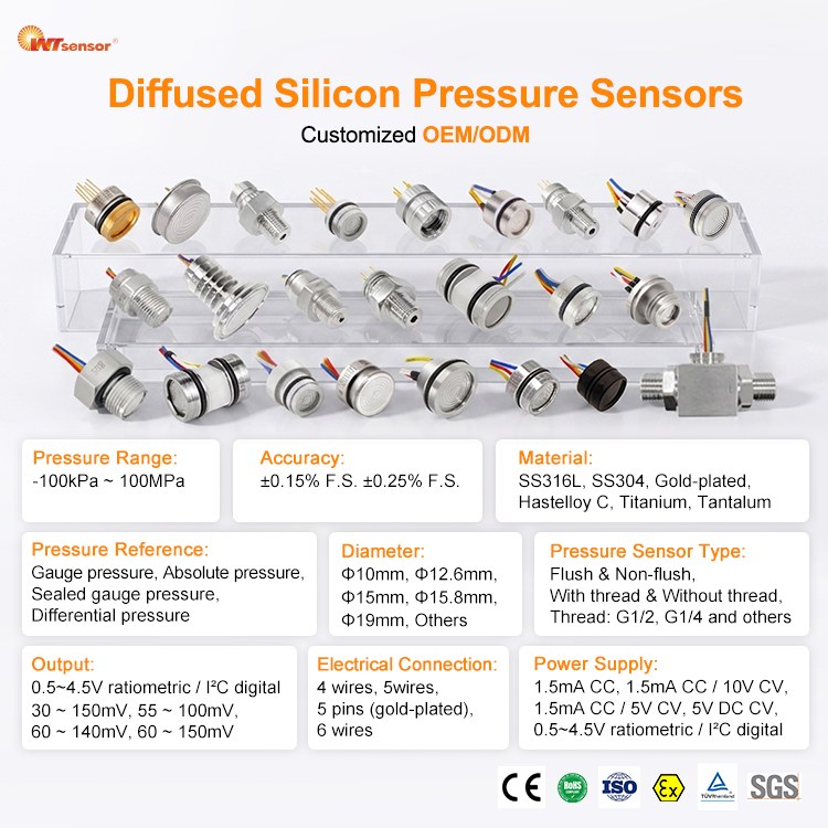
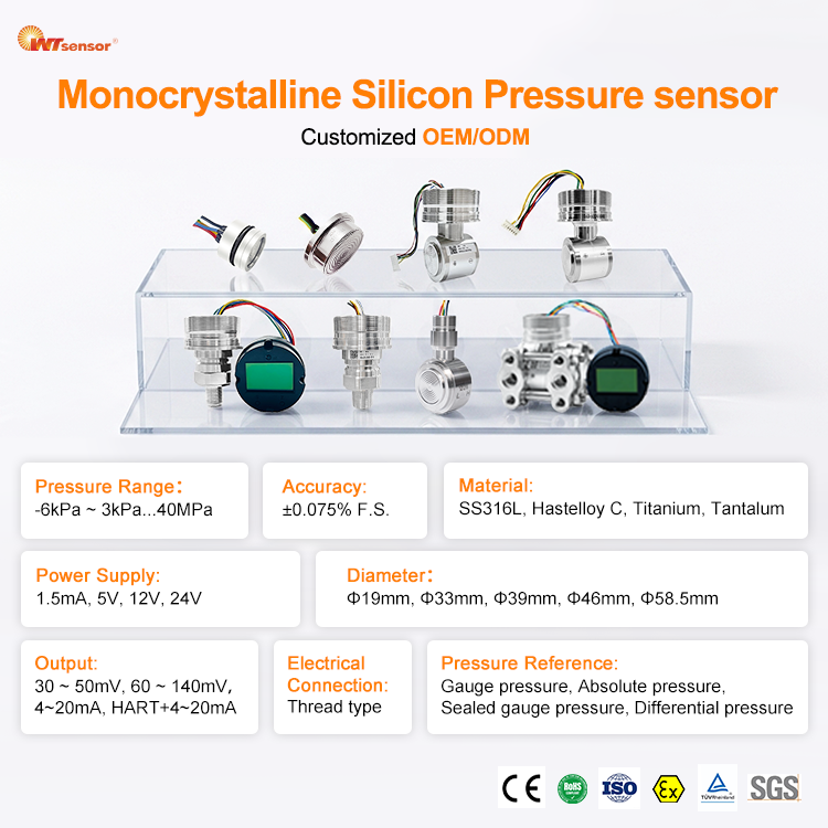
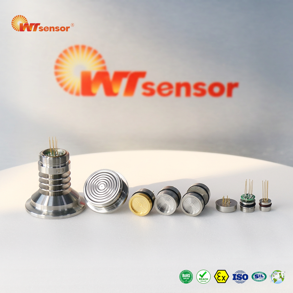
WTsensor builds cores across both axes. Diffused silicon elements cover measuring spans from −100 kPa to 100 MPa, with body diameters from Φ10 mm to Φ19 mm and wetted materials including SS316L, SS304, gold-plated, Hastelloy C, titanium and tantalum. Where the accuracy requirement is tighter, monocrystalline silicon elements are used instead. Differential cores are available in both families — a diffused silicon differential core at ±0.25 %FS, and a monocrystalline silicon differential core reaching ±0.075 %FS — so within the differential line the choice between them is an accuracy decision, not a constraint imposed by the port configuration.
The Eight Decisions at a Glance
| # | Decision | The question it answers |
|---|---|---|
| 1 | Pressure reference | Pressure relative to what? |
| 2 | Range and overpressure | How much pressure, and how much abuse? |
| 3 | Accuracy and thermal compensation | How accurate, and over what temperature? |
| 4 | Output signal | mV, amplified, digital, or current loop? |
| 5 | Electrical connection and supply | How many wires, and powered how? |
| 6 | Diameter and mounting form | Does it physically fit, and how does it seal? |
| 7 | Wetted materials | Will the media attack it? |
| 8 | Sealing and integration | How does it join your product, leak-free? |
These are ordered by how much they constrain everything after them. Decisions 1 to 3 define what the core has to measure. Decisions 4 and 5 define its electrical interface. Decisions 6 to 8 define its mechanical interface. Skipping ahead to the mechanical questions before the measurement questions are settled is an easily overlooked path to an expensive redesign.
Decision 1: Pressure Reference
A pressure reading is meaningless without knowing what it is measured against. This is one of the decisions that is difficult to correct later, because the reference is built into the element and the port arrangement, not into software.
| Reference | Measured against | Typical duty |
|---|---|---|
| Gauge (relative) | Local atmospheric pressure, vented to atmosphere | Pump discharge, hydraulic lines, compressor output, tank level in an open vessel |
| Sealed gauge | A fixed internal reference, sealed at manufacture | Applications where the port is not vented to atmosphere, or where atmospheric variation should not reach the reading |
| Absolute | A sealed vacuum reference | Barometric and altitude-related measurement, vacuum systems, and any reading that has to be a true pressure rather than a difference from atmosphere |
| Differential | The difference between two ports | Flow across an orifice or filter, and level in a closed or pressurised vessel |
The choice between gauge and sealed gauge is the one buyers often leave implicit, and the one that becomes a field problem if they do. A gauge element needs a path to atmosphere — through a vent tube, a cable, or a dedicated vent in the housing. If your finished product has no such path, or if the core will be potted or encapsulated, a gauge element will read something other than what you intended, and it will do so consistently enough to look like a calibration error rather than a reference error.
Sealed gauge and absolute are not the same thing. Sealed gauge uses an internal reference that is not a vacuum, so it reads zero at the pressure it was sealed at, while absolute reads the true pressure including the atmospheric component. For most industrial measurement the difference is small, but for altitude work, vacuum duty, or any application where the reading feeds a calculation, it matters.
Decision 2: Range and Overpressure
Two numbers matter, and buyers frequently specify only the first. The measuring range is the span the core is calibrated over. The overpressure rating, sometimes called burst pressure or proof pressure, is what the element survives without damage or permanent offset.
Selecting a range is a balance. A wide range gives headroom and protects against transients, but it spreads the accuracy over more span, so the same percentage figure represents a larger absolute error. A narrow range gives finer resolution at the working pressure, but leaves less margin for the events that happen during commissioning, cleaning, or a blocked line.
A practical approach is to size the range on the working pressure, allowing for normal fluctuation, and then check the overpressure rating against the highest pressure the element can see — including the pressure spike from a valve closing, a pump starting, or a line being isolated. Those events are usually brief and are frequently omitted from the specification. Where the spike is severe relative to the working pressure, a higher-range element with a correspondingly wider tolerance is often the more robust commercial choice than a better-specified narrow-range element that will be replaced under warranty.
Two further points belong here. First, range and accuracy are not independent: most suppliers quote accuracy as a percentage of full scale, so a 1 MPa range and a 100 MPa range with the same percentage figure are not equivalent in absolute terms. Second, if the process can be cleaned, flushed or sterilised, the peak pressure during that step may exceed normal operation by a wide margin, and it is worth stating explicitly rather than assuming the supplier will allow for it.
Decision 3: Accuracy and Thermal Compensation
Accuracy figures are the easiest part of a specification to compare incorrectly, because the headline number describes only one of several error sources, and the conditions it applies under are often stated in a footnote.
A pressure sensor accuracy specification normally combines several contributions: non-linearity, hysteresis, repeatability, zero offset, and span error. Some suppliers quote these separately, others quote a combined figure. The combined figure is more convenient and less informative, because two cores with the same combined number may behave quite differently in service depending on which term dominates.
Beyond the basic figure, three further specifications change the real-world result:
| Specification | What it covers | Why it matters |
|---|---|---|
| Temperature effect on zero | Zero drift as temperature moves away from the reference | Shows up as an offset that appears only in the field, and is often read as a calibration problem |
| Temperature effect on span | Change in full-scale output with temperature | Scales the reading rather than shifting it, so it is harder to spot from a single data point |
| Long-term stability | Drift over months and years under normal operation | Sets the recalibration interval, and therefore the lifetime cost of ownership |
Together these are what pressure sensor temperature compensation is for. Compensation is applied over a stated temperature range — a compensated range, not the full operating range — and outside that range the specified temperature coefficients no longer describe the behaviour. Some elements are compensated over a narrow band around ambient, others over a range wide enough to cover outdoor and unheated installations. A core rated for a wide operating temperature and a core rated for a wide compensated temperature are not the same product.
This is worth stating plainly, because the distinction is easy to miss when reading a datasheet: When comparing pressure sensor accuracy specifications, always confirm whether the quoted value includes thermal effects or applies only at reference temperature. A figure described as "includes temperature effects" over a stated compensated range is directly comparable. A figure quoted at reference temperature only is the starting point, and the thermal terms have to be added on top to estimate field performance.
Long-term stability deserves the same treatment. A stability figure expressed per year compounds, and over a five- or ten-year service life the accumulated drift may exceed the initial accuracy several times over. Where the instrument is inaccessible, or where recalibration means taking a line out of service, the stability figure is the more important of the two numbers.
For reference: WTsensor core accuracy spans from ±0.5 %FS in the general-purpose range to ±0.075 %FS at the top of the monocrystalline silicon range, with long-term stability figures quoted per year for the higher-stability models.

Decision 4: Output Signal
The output determines how much work you do downstream. There is no answer that applies to every case, only a trade between integration effort, noise performance, and distance.
| Output | Typical form | Trade-off |
|---|---|---|
| Raw mV | Millivolts per unit of excitation, for example 30–150 mV, 55–100 mV or 60–150 mV at the rated excitation | Cheapest core and full control over the signal chain, but you own amplification, temperature compensation, calibration and noise design |
| Ratiometric voltage | 0.5–4.5 V output that scales with the supply | Straightforward to read, and the ratiometric relationship cancels some supply variation, but the output is referenced to the supply |
| Current loop | 4–20 mA, sometimes with HART or RS485 superimposed | Best noise immunity and the standard for long cable runs, but needs more power and adds cost to the core |
| Digital | I²C or a serial interface | Removes analogue error from the board-level signal path, but requires a host that can read it and firmware to match |
The decision follows from distance and environment. A core mounted next to its own signal-conditioning board can use a raw mV output, because the lead length is short and the conditioning can be designed for the specific element. A core at the end of several metres of cable in an electrically noisy plant needs either a conditioned output at the core or careful attention to shielding, grounding and the input stage of whatever reads it.
Raw mV output has a further consequence worth knowing before the specification is frozen: the output is proportional to the excitation, so the excitation and the amplifier have to be treated as one design. Any variation in excitation appears directly in the measured value unless the reading is ratiometric to that same excitation. This is why raw-element specifications state the excitation the output was measured at — without it, the millivolt figure has no meaning.
A further practical point: the output choice interacts with the accuracy discussion in Decision 3. A raw mV element that has been temperature compensated at the element is a different starting point from an uncompensated element, and the difference shows up as additional work on your board rather than as a different number on the core datasheet.
Decision 5: Electrical Connection and Supply
Two things are decided here, and they are usually specified together: how the core is wired, and how it is powered.
Excitation and supply
A raw mV element may be specified for constant-current excitation or for a defined voltage supply, and the two are not interchangeable — a circuit built for one will misread the other. Constant-current excitation is used because the bridge output is then largely independent of the absolute bridge resistance, which reduces the effect of temperature-induced resistance changes. Driving the same element from a constant voltage leaves that dependence in place, and the resulting error appears as a temperature effect on span.
The required excitation is set by the manufacturer for the specific element and is confirmed against the core datasheet. On the WTsensor diffused silicon core range, the standard supply options are 1.5 mA constant current, 1.5 mA constant current combined with a 10 V or 5 V constant voltage supply, 5 V DC constant voltage, and a 0.5–4.5 V ratiometric supply with an optional I²C digital output. The correct option depends on the element and on the output format chosen in Decision 4, and the value quoted for one does not carry over to another.
Conditioned elements instead accept a defined voltage supply, and the output is read directly. In that case the specification to confirm is the supply range the element tolerates, including the behaviour below the minimum supply — some elements produce a misleading output rather than an obviously invalid one when the supply sags.
Wiring
| Arrangement | When it is used |
|---|---|
| 4 wires | A bridge element wired with separate excitation and signal pairs, which removes the lead resistance from the measured value |
| 5 wires | As above with an additional connection, typically a screen or a second signal reference |
| 6 wires | Where a separate sense pair or additional shielding is required |
| Pins (gold-plated) | Where the core is soldered or socketed directly onto a board rather than supplied with leads |
Wiring is where a specification that looked complete turns out not to be. The number of wires, the colour code, the lead length, the lead material, the pin pitch and the pin plating all have to be fixed, and any of them may need to change for an OEM variant. Gold plating on the pins is the usual choice where long-term contact resistance matters or where the assembly is exposed to humidity during storage.
Two details cause a disproportionate share of integration problems. The first is lead length: a specification that names a wire count but not a length will be built to a nominal value, and if your assembly needs a different one, the change is easy to make at the factory and awkward to make on the line. The second is the wiring convention for differential and pressure-reference variants, where the sense of the output relative to the two ports has to be stated rather than assumed — a differential core wired the wrong way round produces a reading that is internally consistent and points the wrong direction.
Decision 6: Diameter and Mounting Form
This is where the specification meets the physical product, and where an otherwise ideal core turns out not to fit. Three dimensions are involved, and they constrain each other: the body diameter, the thread or fitting, and the sealing face.
Body diameter sets how much space the core needs inside your housing and, in many designs, how large the housing has to be. A smaller diameter element is easier to package, but usually carries a narrower measuring range or a lower overpressure rating, because the diaphragm area available to act on the element is smaller. Common body diameters in the diffused silicon range run from Φ10 mm up to Φ19 mm, with options at Φ12.6 mm, Φ15 mm and Φ15.8 mm in between.
| Mounting form | How it seals | Where it is used |
|---|---|---|
| Threaded, non-flush | Thread seal, or a gasket or O-ring at a face | The standard arrangement for clean, non-viscous media |
| Threaded, flush diaphragm | Gasket or O-ring at the flush face | Media that would clog or crystallise in a cavity |
| O-ring seal, no thread | Radial or face O-ring against a machined bore | Compact assemblies where the core is clamped into the housing |
| Sanitary clamp | Clamp gasket on a hygienic face | Food, dairy and pharmaceutical duty |
| Welded or brazed into the assembly | A metallurgical joint, no elastomer in contact with the media | High-integrity duty, and where no elastomer is permitted in the wetted path |
Two mounting details are frequently left out of a first specification and cause rework later. The first is the thread standard: a nominal size such as G1/4 is not unique once the standard, the sealing form and the thread length are taken into account, and the same nominal size can be supplied in forms that do not interchange. The second is the wrenching or clamping feature — whether the assembly is tightened by a hex, a spanner flat or a dedicated tool, and whether that feature survives the tightening torque in a production environment.
If the core is to be screwed into a manifold or a machined block, it is worth confirming that the mating thread and the sealing face are defined by the same drawing, rather than assuming compatibility between two specifications that each look standard on their own.
Decision 7: Wetted Materials
The wetted materials are the diaphragm, the body or the housing that contacts the process, and any seal in the wetted path. This decision is driven entirely by the medium, and getting it wrong produces failures that appear months later and are expensive to diagnose.
| Material | General suitability | Points to note |
|---|---|---|
| SS316L | The default for a wide range of industrial media, including water, oils and many process fluids | Not suitable for all chlorides at elevated temperature, and not for all aggressive chemicals |
| SS304 | Non-aggressive media, and where SS316L is not required | Lower corrosion resistance than SS316L, and the difference matters in wet or chloride-bearing service |
| Hastelloy C | Aggressive media and chloride-bearing duty where an austenitic stainless steel corrodes | Appreciably more expensive, so usually specified only where the medium requires it |
| PTFE-coated | Media that must not contact metal, and some strongly reactive chemicals | The coating is a barrier, and damage to it exposes the base metal underneath |
| Titanium | Some chloride and oxidising environments, and where low density is helpful | Not a general-purpose substitute for stainless steel; suitability is specific to the medium |
| Tantalum | Highly aggressive chemical duty | A specialist choice, with cost and availability implications |
| 17-4PH | Higher-pressure duty where a stainless steel with higher strength is wanted | Corrosion behaviour differs from the 300-series grades |
| Gold-plated | Applied to contact surfaces rather than to a wetted diaphragm | Used for contact reliability in electrical connections and stored assemblies |
Two practical rules apply here. The first is that compatibility is a property of the medium, the concentration, the temperature and the material taken together — not of the material alone. A grade that performs well at ambient temperature in a dilute solution may behave differently at elevated temperature or higher concentration, so the operating conditions belong in the specification alongside the medium name.
The second is that the seal is often the limiting item rather than the metal. An O-ring in the wetted path may have a narrower temperature range, or a different chemical compatibility, than the diaphragm and body around it, and it is the component that ages. If the medium is aggressive, the sealing material needs the same scrutiny as the diaphragm.
Decision 8: Sealing and Integration
This decision determines whether the core becomes a reliable product or a warranty problem, and it is the one often treated as a detail to be settled at assembly time.
A core presents several joints that all have to remain leak-tight: the joint to the process, the joint between the element and its body, and the electrical feedthrough that carries the signal out through the housing wall. The first is a sealing decision you make, using a gasket, an O-ring or a weld. The second is normally made at the factory. The third sits in between, and it is the one buyers ask about least and reliability engineers care about most, because a leak path through the electrical feedthrough puts the medium in contact with the electronics regardless of how well the process joint is made.
The temperature range of the finished assembly is also set here rather than by the element alone. The core may be rated over a wide range, while the seal, the potting compound or the cable has a narrower one, and the assembly rating is the narrower of the two. Where the finished product is qualified as a whole, the qualification is against the assembly's rating, not the core's.
Integration choices that belong in the specification include:
The mounting torque the assembly is designed for, and whether the core is intended to be installed with a torque wrench or a fixture.
Whether the joint is to be welded, brazed, crimped or sealed with an elastomer, and if welded, whether the heat input is acceptable to the element.
The leak-test method and acceptance criterion for the finished assembly — helium leak testing, pressure decay, or bubble test — and at what stage it is performed.
Whether the cable or lead exit is strain-relieved, and how much pull the assembly is expected to survive.
Whether the core will be potted, overmoulded or encapsulated, and whether the process temperature involved is acceptable to the element.
The last item deserves emphasis, because potting and overmoulding are the steps where a correctly specified core is often damaged. The temperature and pressure of the moulding process, and the shrinkage of the compound as it cures, both act on the element. A core that performs correctly on the bench may show a permanent offset after encapsulation, and the cause is the process rather than the core. If the finished product involves either step, it belongs in the original enquiry, so the manufacturer can supply an element suited to it.
Core, Module, or Complete Transmitter?
A core is one of several forms in which a sensing element is supplied, and the three options carry very different amounts of work.
| Form | What you receive | What you still have to do |
|---|---|---|
| Core (element) | The sensing element and its mechanical boundary, with a raw or lightly conditioned output | Signal conditioning, compensation, calibration, housing, connector, marking and documentation |
| Module | An element with signal conditioning and often compensation already integrated, usually on a small board | Packaging, connector, final calibration and documentation |
| Complete transmitter | A finished instrument with a defined output, electrical connection and housing | Selection, integration and any application-specific certification |
The transition between these forms is a commercial decision as much as a technical one. A core gives the lowest unit cost and the greatest control over the finished product, and it is the right choice where you have the engineering resource to own the signal chain and the calibration. A module or a complete transmitter costs more per unit and reduces the work on your side, which is the right choice where volume does not justify the engineering, where lead time matters more than unit cost, or where the finished product has to carry a certification you would rather inherit than obtain yourself.
A frequent and easily avoided mistake is to specify a core for a product that has no resource to develop the signal chain around it. The result is a longer development cycle than a module would have needed, and a higher total cost than the more expensive component. It is worth deciding which of the three forms you are buying before working through Decisions 1 to 8, because the answers change depending on the answer to this question.
Where Pressure Sensor Cores Are Used
Core selection is not specific to one industry, and it is worth seeing the range of duties, because requirements from one area often transfer to another.
| Application area | Typical duty | Decisions that dominate |
|---|---|---|
| Industrial automation | Pneumatic and hydraulic line pressure, actuators, clamping and forming equipment | Range and overpressure, output signal, mounting form |
| Water and wastewater | Pump discharge, filter differential, level in tanks and wet wells | Pressure reference, wetted materials, sealing |
| HVAC and building services | Chilled and hot water circuits, filter differential, air-side pressure | Low-range accuracy, temperature effects, cost |
| Food and pharmaceutical | Hygienic process lines, CIP and SIP duty | Flush mounting, wetted materials, temperature range of the assembly |
| Oil, gas and energy | Line pressure, filter monitoring, level in closed vessels | Wetted materials, pressure reference, sealing, certification |
| Medical and analytical equipment | Gas and liquid pressure in instruments, small-volume measurement | Small diameter, low range, non-metallic wetted options, repeatability |
| Vehicle and off-highway | Fluid pressure monitoring on mobile equipment | Vibration and temperature range, overpressure, electrical connection |
Two patterns are worth noticing in that table. The first is that differential measurement appears across several areas for the same underlying reason — a pressure difference is a direct indication of flow across a restriction or of the state of a filter — so the differential decisions carry across industries more than the others. The second is that the hygienic and aggressive-media applications are the ones where the mechanical and material decisions, rather than the measurement decisions, determine whether the product succeeds.
Worked Specification
A specification is easier to write against an example. The following describes a core for an OEM pressure transmitter intended for general industrial use, in a housing of the customer's own design.
| Parameter | Requirement | Why |
|---|---|---|
| Pressure reference | Gauge, vented | Reads pressure relative to atmosphere; the housing provides a vent path |
| Measuring range | 0–1.6 MPa | Covers the working pressure with headroom, while keeping the absolute error per percent of scale small |
| Overpressure | At least 2× the measuring range, confirmed against the datasheet | Allows for start-up transients and line isolation without permanent offset |
| Accuracy | ±0.25 %FS, combined figure | Sufficient for the application without paying for a high-accuracy element |
| Compensated temperature range | Covering the intended operating range, stated explicitly | Outside it, the quoted coefficients do not describe the behaviour |
| Output | Raw mV, ratiometric to the excitation | Short lead length to the customer's own board; no benefit from conditioning at the core |
| Excitation | As specified by the manufacturer for the element | The output figure is only meaningful at the stated excitation |
| Electrical connection | 4 wires, defined length and colour code | Removes lead resistance from the measured value |
| Body diameter | Φ15.8 mm nominal | Fits the machined housing with clearance for the seal |
| Mounting | Threaded, non-flush, with O-ring seal | Clean medium; no requirement for a flush face |
| Wetted materials | SS316L diaphragm and body; seal compatible with the medium | Standard choice for the medium in question |
| Electrical feedthrough | Hermetically sealed | Prevents a leak path through the signal connection |
| Marking | Customer part number and traceability code | Required for the customer's own quality system |
Several entries in this table are conditions rather than absolute values, and that is deliberate. The overpressure requirement is expressed as a multiple that has to be confirmed against the supplier's datasheet, because the ratio varies between models. The excitation is expressed as "as specified by the manufacturer", because the correct value depends on the element and the output format. Writing a specification this way makes the dependencies visible instead of hiding them behind numbers that look precise but were not verified.
Common Selection Mistakes
The mistakes below appear repeatedly in enquiries, and most are corrected cheaply at the specification stage and expensively afterwards.
Selecting a range that is too wide "for safety". A wider range protects against transients, but if accuracy is quoted as a percentage of full scale, the absolute error grows with it. A core with the right range and a suitable overpressure rating often serves better than an oversized one.
Treating gauge and sealed gauge as interchangeable. They are not, and the difference appears as a consistent offset rather than as an obvious fault. If the finished product has no vent path, gauge is the wrong reference regardless of how the specification reads.
Comparing accuracy figures without comparing their conditions. A figure quoted at reference temperature and a figure that includes thermal effects over a compensated range are not comparable, even when the numbers look similar.
Leaving the electrical connection partly undefined. A wire count without a length, a colour code or a pin plating is an incomplete specification, and the gap is filled at the factory by a nominal value that may not match the assembly.
Specifying the wetted material without the medium conditions. Compatibility depends on concentration and temperature as well as on the material, so a material name on its own does not establish that the core is suitable.
Omitting the assembly process from the enquiry. Welding, potting and overmoulding all act on the element. Where they are part of the finished product, they change which element is appropriate.
Confusing an operating temperature range with a compensated one. A wide operating range describes what the element survives. The compensated range describes where the specified accuracy holds. They are different figures.
Ordering a core for a product with no signal-chain resource. This produces a longer development cycle than specifying a module would have needed, at a higher total cost.
What to Send a Sensor Manufacturer: RFQ Checklist
A complete enquiry produces an accurate quotation quickly. An incomplete one produces either a request for clarification or a quotation with assumptions built in, and the assumptions are where the surprises come from. Quotation delays often come from missing inputs rather than from the manufacturing side.
Measurement
Pressure reference: gauge, sealed gauge, absolute or differential
Measuring range, in the units you actually work in, with the working pressure stated separately if it differs from the range
Required overpressure or proof pressure, if you know it
Accuracy requirement, and whether it includes thermal effects
Compensated temperature range, and operating temperature range
Long-term stability expectation, if the recalibration interval matters
Electrical
Output format, and the value it refers to
Excitation or supply, if you have a preference
Number of wires, lead length, colour code, pin plating and pitch
Whether the assembly must carry any certification, and which
Mechanical
Body diameter and any envelope constraints
Mounting form and thread standard, with the sealing method
Wetted materials, including the seal
Whether the core is welded, brazed, potted or overmoulded into the assembly
Leak-test method and acceptance criterion, if defined
Commercial
Annual or first-order quantity, and whether the requirement is expected to grow
Marking, labelling and traceability requirements
Documentation required with the shipment, such as a test certificate or a material declaration
Required delivery date and destination
Any sample or qualification process the order has to pass before volume supply
If some of these are not yet decided, saying so is more useful than leaving them out. A manufacturer who knows which items are open can propose options and quote them as alternatives, which is a faster route to a decision than a specification that appears complete but contains assumptions on both sides.
Where to Go Next
The decisions above connect to more detailed material elsewhere on this site. Depending on which one is currently open, the following pages go deeper.
Sensing technologies
Diffused silicon pressure sensors — the mainstream family, and the range of bodies, ranges and diaphragm materials available in it.
Monocrystalline silicon pressure sensors — where the tighter accuracy and stability ceiling applies, and what it costs.
Internal structure of a diffused silicon pressure sensor — what sits behind the diaphragm, part by part.
Piezoresistive pressure sensors: diffused silicon vs monocrystalline silicon — how the two silicon families differ in principle and in application.
Differential measurement
Monocrystalline silicon differential pressure sensors — the higher-accuracy end of the two-port range.
Differential pressure transmitters — the finished-instrument side of the same measurement.
Finished instruments
Pressure transmitters — the range built around these cores, where the integration has already been done.
Level sensors and transmitters — hydrostatic level measurement, which follows Decisions 1 and 2 closely.
Submersible level transmitter selection guide — the full selection process applied to a specific product family.
Construction, sealing and the sensing boundary
Glass-to-metal seal manufacturer guide — the hermetic feedthrough that keeps the electrical side dry.
Hermetic sealing — sealed connectors, headers and feedthroughs for instrument assemblies.
Metal bellows guide — the separate sensing element used where a diaphragm is not the right boundary.
About WTsensor
WTsensor (Nanjing Wotian Technology) has manufactured pressure sensors since 2005. Its core business is the sensing element itself: diffused silicon and glass micro-fused elements supplied both as standalone cores for OEM integration and built into its own finished instrument range. Quality systems are certified to ISO 9001 and IATF 16949, and the core range is covered by CE, RoHS, REACH and EMC documentation.
Core options span gauge, absolute, sealed-gauge and differential references, measuring spans from −100 kPa to 100 MPa, body diameters from Φ10 mm to Φ19 mm, and wetted materials including SS316L, SS304, gold-plated, Hastelloy C, titanium and tantalum. Differential cores are available in both diffused silicon and monocrystalline silicon constructions, the latter reaching ±0.075 %FS. Because these are elements rather than finished instruments, most requirements are built to order and configured against the customer's own product.

For OEMs looking for a pressure sensor core manufacturer, WTsensor can configure core diameter, output, excitation, wiring, materials and marking around the finished product requirements. Final specifications are confirmed against the current datasheet at quotation.
FAQ
What is the difference between a pressure sensor core and a pressure transmitter?
A core is the sensing element and its mechanical boundary, with a raw or lightly conditioned output. A transmitter is a finished instrument that adds signal conditioning, a defined output, an electrical connection and a housing. Choosing between them is a question of how much of the signal chain you intend to own.
Can I use a gauge core in a sealed housing?
A gauge element needs a path to atmosphere to work as intended. In a sealed housing with no vent, it will read relative to whatever pressure was trapped inside at assembly, which appears as a constant offset. Where the housing is sealed, a sealed-gauge or absolute element is the appropriate choice.
Should I choose diffused silicon or monocrystalline silicon?
Both are silicon piezoresistive. In practice the choice usually follows accuracy and stability requirements: diffused silicon covers the mainstream range, while monocrystalline silicon is selected where the reference accuracy and long-term stability need to be tighter. Within the differential range both are available, so the choice there is an accuracy decision rather than a question of what the port configuration allows.
How do I compare two accuracy specifications that quote the same number?
Establish what each figure covers and under what conditions. A combined figure that includes thermal effects over a stated compensated range is directly comparable with another figure of the same kind. A figure quoted at reference temperature only is not, because the thermal contributions have to be added to estimate performance in service.
What excitation does a raw mV core need?
The excitation is specified by the manufacturer for the individual element, and the output figure is only meaningful at the excitation it was measured at. Constant-current excitation is used where the output should be largely independent of bridge resistance. Confirm the requirement against the datasheet for the specific core rather than assuming a value carries across models.
How long does a typical core order take?
Lead time depends on the configuration, the quantity and whether the requirement is a standard model or a customer-specific variant. Because much of the core range is built to order, it is worth including the required delivery date in the enquiry so it can be quoted against directly.
- Read More >
-
Inside Differential Pressure Sensor Core Manufacturing: From Gold Wire Bonding to Final Protection
Read More > -
How Welded Pressure Transmitters Prevent Leakage Before Calibration
Read More > -
Why Temperature Transmitters Drift—and How Our Production Process Prevents It
Read More > -
What is a Glass-to-Metal Seal? Complete Guide for Engineers
Read More > -
What is a Wireless Pressure Sensor? Complete Guide for Industrial IoT
Read More > -
How to Choose a Pressure Transmitter: A Complete Selection Guide
Read More > -
Hydrostatic Level Measurement: How to Select a Submersible Level Transmitter
Read More >
This article Tags: pressure sensor diffused silicon monocrystalline silicon differential
Back to List