 Pусский

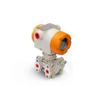
PCM3051 Differential Pressure Transmitter Selection and Ordering Guide
From: Issued date 2026.10.28 Back
This guide covers one thing: how to choose and how to order inside the PCM3051 family. It assumes you have already decided that a differential pressure measurement is the right one. If the measurement is gauge or absolute pressure rather than a difference between two points — a steam header, firefighting pipework, a single tapping on a line — the PCM2051 line is the equivalent family, and the firefighting pipe case is written up separately in monocrystalline silicon pressure transmitters for firefighting pipe systems. If that decision is still open, the working principle of differential pressure sensors is the place to start. If you know the principle and want to know how the sensing element is built, read differential pressure sensor core manufacturing. If you have already bought one and it is misbehaving, the pressure transmitter troubleshooting checklist is the faster route.
What the PCM3051 family actually contains
The name covers four transmitters that share a monocrystalline silicon differential pressure sensor and a 4–20 mA + HART two-wire output, and differ in how the process pressure reaches the diaphragm. That difference, not the electronics, is what decides which one an application needs.
| Model | Construction | Pressure ranges (datasheet) | Accuracy | Wetted path |
|---|---|---|---|---|
| PCM3051-DP | Differential, direct process connection | ±1 kPa, ±6 kPa, ±40 kPa, ±100 kPa, ±250 kPa, ±1 MPa, ±3 MPa | ±0.2 %FS at ±1 kPa; ±0.1 %FS at ±6 kPa; ±0.075 %FS on the other five ranges | 316L or Hastelloy C diaphragm, silicone oil fill, silicone O-ring |
| PCM3051-LT | Single flange, side-mounted level | 0–6 kPa through 0–3 MPa | ±0.1 %FS (25 ± 5 °C, standard ranges) | 316L, Hastelloy C or tantalum diaphragm |
| PCM3051-RG | Single-flange remote seal | −6–6 kPa through −0.1–3 MPa | ±0.1 %FS (standard ranges) | Diaphragm same options; fluororubber O-ring |
| PCM3051-RD | Double-flange remote seal | −6–6 kPa through −0.1–3 MPa | ±0.1 %FS (standard ranges) | Diaphragm same options; fluororubber O-ring |
Two things in that table are worth stopping on, because both are easy to misread in an enquiry.
The first is accuracy. The figures are not one number for the family. On the DP, ±0.075 %FS applies to five of the seven ranges and stops applying at the two smallest, where it becomes ±0.1 %FS and then ±0.2 %FS. A requirement written as "accuracy 0.075 %" alongside a range of ±1 kPa is, on this datasheet, asking for something the range code does not offer.
The second is that all four models are rated IP67, but the explosion-proof grade is not uniform across the family: the DP is published as Ex d IIC T6 Gb, while the level and remote-seal variants are published under a different group. Because a certificate is issued against a configuration rather than against a model name, the grade for the exact model and housing you are ordering is the one to confirm. The datasheet also names J12X and J22X as the explosion-proof housings and lists J8X and J8 alongside them as grey-and-white housings. The grade printed in the performance table is a model-level figure; where a model or a housing differs, the certificate for that exact configuration governs, and it is the document worth asking for. Because a certificate is issued against a configuration rather than against a model name, a classified-area enquiry is best written with the housing, the display and the cable entry stated together, and with a request for the certificate that covers that exact combination.
Decision 1: the range code decides more than the range
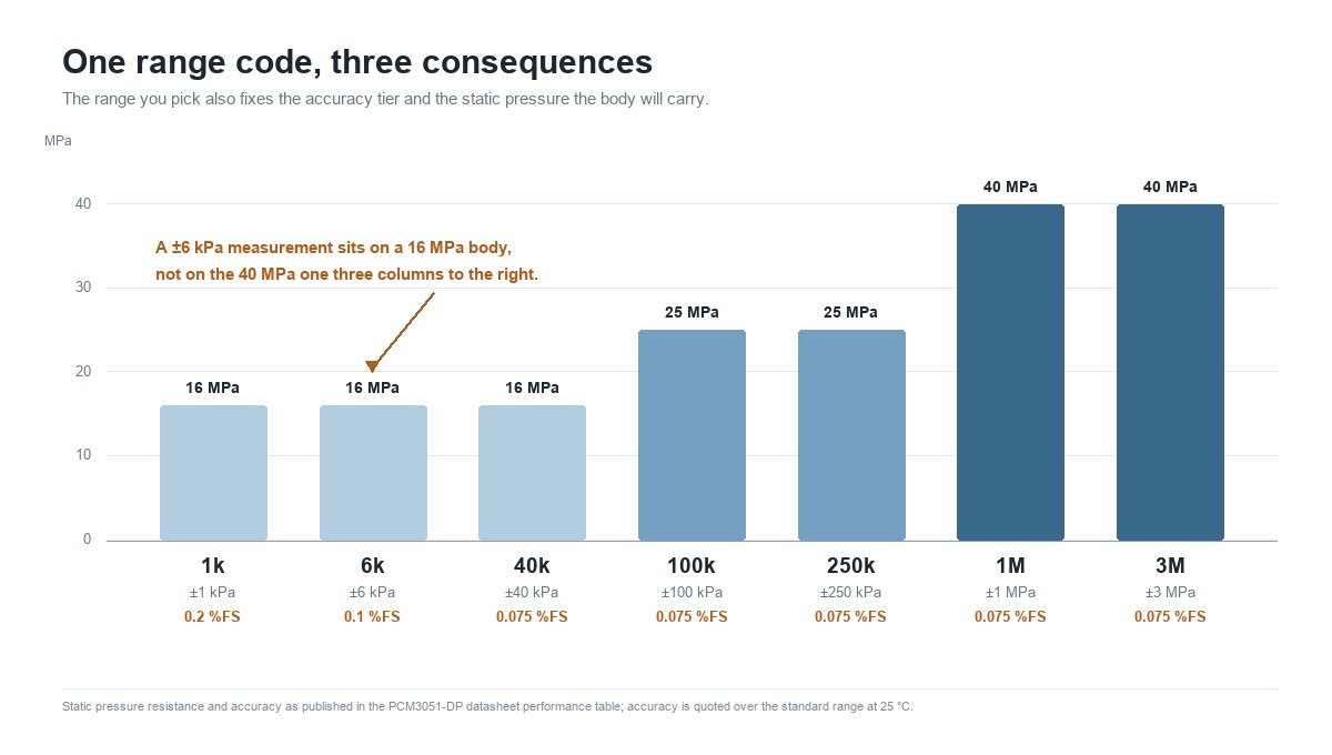
Start with the range, because on this family the range code sets three other things at once: the accuracy tier, the static pressure the body will take, and the overload limit.
| Range code | Span | Accuracy | Temperature drift (−20 °C to 70 °C) | Static pressure resistance |
|---|---|---|---|---|
| 1k | ±1 kPa | ±0.2 %FS | ±0.5 %FS | 16 MPa |
| 6k | ±6 kPa | ±0.1 %FS | ±0.3 %FS | 16 MPa |
| 40k | ±40 kPa | ±0.075 %FS | ±0.25 %FS | 16 MPa |
| 100k | ±100 kPa | ±0.075 %FS | ±0.25 %FS | 25 MPa |
| 250k | ±250 kPa | ±0.075 %FS | ±0.25 %FS | 25 MPa |
| 1M | ±1 MPa | ±0.075 %FS | ±0.25 %FS | 40 MPa |
| 3M | ±3 MPa | ±0.075 %FS | ±0.25 %FS | 40 MPa |
Read the last column as a staircase. A ±6 kPa measurement is not carried by a 40 MPa static-pressure body; it is carried by a 16 MPa body. Buyers who need a small span on a high-line-pressure process often assume they can specify the small range and keep the high static rating, and the table does not work that way. If the line pressure is above the static resistance of the range you need, the range is not the variable to move — the measurement method is.
Static pressure resistance and the overload limit are two different ratings and are not interchangeable: one describes continuous operation, the other a transient condition. The table gives the static figure for each range, and the datasheet gives a single overload figure for the DP. A buyer who needs both a small span and a high line pressure has to read both numbers, because the range code sets them together.
Decision 2: the static pressure error is a separate specification line
On the remote-seal models the datasheet publishes a static pressure effect that has no equivalent on the DP: zero shifts by 0.15 %FS and span by 0.25 %FS for every 4 MPa of static pressure. That is a per-4-MPa figure, and it scales. It is not covered by the accuracy number, it is not covered by the temperature drift figure, and it is the line a comparison easily leaves out.
The practical consequence is that two installations of the same instrument on the same range can end up with different real accuracy, because one sits at 1 MPa line pressure and the other at 10 MPa. If the process line pressure is high, ask for the static pressure effect at your actual pressure rather than accepting the headline accuracy. A ±0.1 %FS instrument on a 12 MPa line is not delivering ±0.1 %FS of the reading.
Decision 3: temperature drift, not accuracy, sets the real error budget
Put the accuracy row and the drift row side by side. On a 100k range the accuracy is ±0.075 %FS and the temperature drift is ±0.25 %FS across −20 °C to 70 °C. The drift term is more than three times the accuracy term.
This is not a criticism of the instrument; it is how the specification is built, and every supplier in this class publishes both numbers. The point is that the number a plant experiences over a year is closer to the drift figure than to the accuracy figure, unless the ambient is held near 25 °C. A control room installation and an outdoor installation of the same transmitter are not the same measurement.
What the datasheet does not do is break the drift figure down per degree. So the correct reading is not "this instrument drifts 0.25 %FS in my plant". It is: across the full published band the temperature contribution reaches that magnitude. It should not be read as varying linearly with temperature unless characterisation data for the model supports that reading, so a narrower band does not automatically mean a proportionally smaller error. Ask for the temperature-error data for the model rather than interpolating the band figure.
Decision 4: DP, LT, RG or RD — the question is where the diaphragm sits
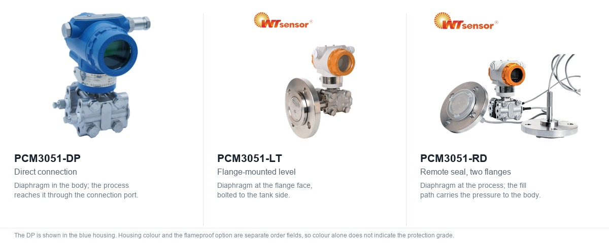
All four models measure the same physical quantity. What separates them is whether the isolating diaphragm sits at the end of the transmitter body, bolted directly to a flange, or at the end of a fill-fluid path that carries the pressure back to the body.
Direct connection, PCM3051-DP
The diaphragm is inside the body and the process reaches it through the connection port. There is no fill path between the process and the sensor, so the response is immediate and there is nothing extra to keep at temperature. This is the model for clean, non-solidifying, non-crystallising media: air and gas flow across an orifice plate, filter differential, clean water, steam through a condenser, pump differential.
The limitation is the connection itself. A small port on a process line is a place where a process can solidify, freeze or plug. When that happens the measurement does not fail loudly; it slowly stops responding, and the drift looks like a sensor problem. If the medium can set in a dead leg, a direct connection is the wrong construction regardless of how good the sensor is.
Flange-mounted level, PCM3051-LT
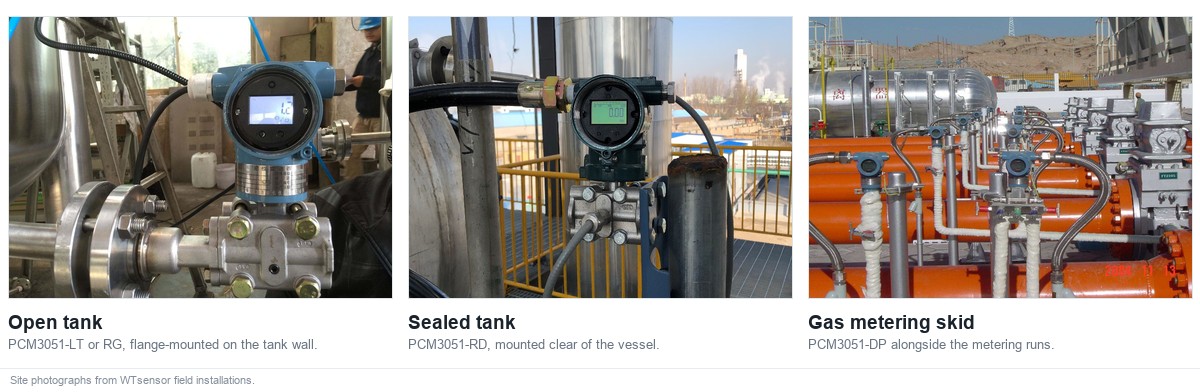
The diaphragm is on a flange face that bolts straight to a nozzle, so the wetted surface is flush with the vessel wall and there is no pocket for the process to collect in. Used on the side of a tank for level and density, using the difference between two tappings or between one tapping and a reference leg.
Because the flange face is the diaphragm, the flange standard and size are not an afterthought: they are part of the measurement. The datasheet orders the flange separately from the diaphragm material, with F1 at DN25 PN40 RF, F2 at DN40, F3 at DN50 and F4 at DN80 PN16 RF, and the diaphragm material as M1 Hastelloy C, M2 tantalum or M4 316L.
Remote seal, PCM3051-RG and PCM3051-RD
These put the diaphragm out at the process and carry the pressure back to the body through a fill fluid. RG seals one flange, and is used where one side of the measurement needs a seal — a level measurement against a reference leg, or a flow measurement where only the high side is on a dirty line. RD is the double-flange version, where both sides need sealing: two flanges on two tappings, or a differential across two vessels.
The reason to choose them is process contact, not accuracy. A remote seal is the answer when the medium is hot enough that a direct-mounted body would exceed its ambient or medium limit, when it is corrosive enough that the wetted material has to be Hastelloy C or tantalum, when it is viscous or contains solids that would plug a port, when it can crystallise on a cold surface, or when the process has to be opened for cleaning and the instrument must come off without breaking containment.
What the construction costs has to be stated as plainly as what it solves. The fill fluid sits between the process and the sensor, so the fill fluid's own temperature behaviour enters the measurement, and the fill path adds a thermal lag that shows up as a slower response to a step change. A remote seal on a fast loop is a slower instrument than a direct connection, and that is a property of the construction rather than a defect. Long fill paths also need care at commissioning, because an air pocket in the path has to be removed before the reading means anything.
One ordering boundary belongs here, because it is a frequent correction. The remote-seal models take standard differential ranges up to 3 MPa, with the range list running from −6–6 kPa to −0.1–3 MPa. A 40 MPa figure belongs to static pressure capability or to a different product route; it is not a standard differential range for RD or RG. If a requirement arrives as "40 MPa differential", the requirement needs discussing before it becomes a model code, not after.
Decision 5: wetted materials and the fill fluid
The datasheet offers 316L as the default diaphragm, Hastelloy C as the upgrade, and tantalum on the LT, RG and RD. The choice follows the medium, and it is worth resisting the reflex of specifying Hastelloy everywhere. Hastelloy C is the usual direction for chlorides and oxidising conditions, tantalum for hydrochloric acid and media that attack the alternatives, and 316L for clean water, air, steam and non-aggressive fluids. That is a starting point rather than an approval: compatibility depends on concentration, temperature, impurities and the specific alloy grade, so a final selection is confirmed against the medium data rather than by alloy family name.
One option sits outside the M-codes. A gold-plated 316L diaphragm is offered for hydrogen service, where atomic hydrogen can permeate a bare stainless diaphragm. Because plating is a surface treatment rather than a material grade, it is not an entry in the ordering table, so it has to be stated in the enquiry rather than picked from a code list.

Two details in the datasheet matter more than they look. On the DP the O-ring in contact with the medium is silicone rubber; on the RG and RD it is fluororubber. If the medium attacks silicone oil or silicone rubber, the direct-connection model is the one that has to be examined, because the O-ring is part of the wetted path whether or not it appears on the process drawing. And the fill fluid on the DP is silicone oil, which sets a medium temperature ceiling of 125 °C; above that the conversation moves to a different construction rather than a different code.
For hygienic and pharmaceutical duties the flange face and surface finish matter as much as the alloy, and those are specified with the flange rather than the diaphragm. A 316L diaphragm on a flange that has a crevice at the joint is not a hygienic installation.
Decision 6: housing, connection and manifold
The electrical connection code carries the housing and the display in one field, which is convenient until it is misread. On the DP, J8X is a grey-and-white housing with display on M20×1.5, J8 the same housing without display, J12X a blue explosion-proof housing with display on M20×1.5, J22X the same on NPT 1/2 female, and J12 and J22 the versions without display. The remote-seal and flange-mounted models offer J8X, J12X and J22X with display.
So one field is answering three questions at once: does it have a local display, is the housing the explosion-proof one, and what is the cable entry thread. For a classified area the second question is the one to settle first, and the datasheet identifies J12 and J22 as the explosion-proof housings.
The process connection field is where a differential transmitter stops looking like a pressure transmitter. The DP offers C1 at M20×1.5 with welded pipe, C2 at G1/2 with welded pipe, C3 at G1/4 male, C5F at NPT 1/4 female as the default, C7 at NPT 1/2, C7F at NPT 1/2 female, and two integrated three-valve manifold options, SFZC1 at M20×1.5 with welded pipe and SFZC5F at NPT 1/4 female.
The manifold choice is a commissioning decision disguised as a part number. A three-valve manifold lets the transmitter be equalised and isolated without dismantling the impulse lines, which is the difference between a zero check that takes five minutes and one that takes an hour and risks the process. On a differential measurement the manifold is not an accessory to be added later; it changes what the installation can be maintained like.
The mounting bracket is the last field in the order, and it is the one an enquiry tends to leave out. The datasheet offers three: B1, a pipe-mounted bending bracket for a horizontal tank, B2, a panel-mounted bending bracket, and B3, a pipe-mounted flat bracket for a vertical tank. The choice follows where the transmitter physically sits, and a bracket that arrives in the wrong form is a second shipment rather than a field modification.
Where each model is normally used
| Duty | Model | Why that one |
|---|---|---|
| Flow across an orifice or venturi | PCM3051-DP | Clean gas or liquid, direct connection, no fill path to lag the response |
| Filter and strainer differential | PCM3051-DP | Small span, gas or liquid, element change does not require removing the transmitter |
| Closed-tank level against a reference leg | PCM3051-DP or PCM3051-RG | DP where the wet leg is clean, RG where only the process side needs sealing |
| Open-tank or side-mounted level | PCM3051-LT | Flush flange face, no pocket at the vessel wall |
| Hot, corrosive, viscous or crystallising medium | PCM3051-RG or PCM3051-RD | Diaphragm at the process, transmitter body away from it |
| Differential between two sealed process points | PCM3051-RD | Both sides need a seal, not just the high side |
| Density and interface measurement | PCM3051-LT or PCM3051-RD | Differential head over a fixed height, flanged to suit the vessel |
The application pages already on this site go deeper on several of these duties and are worth reading alongside this guide: differential pressure transmitters in power, clean rooms and textiles, and precision flow monitoring in gas regulator stations. This guide deliberately does not repeat them; it stops at the model and the code.
A worked specification, field by field
Take a real shape of requirement: differential pressure across a coalescing filter on a compressed air line. Normal differential is a few kilopascals, alarm at 5 kPa, line pressure 0.8 MPa, indoor installation, no classified area, the maintenance team wants to read the value at the transmitter and zero it locally, and the medium is dry air.
Working through the fields in order:
- Model. Clean gas, direct connection, no risk of the port setting. PCM3051-DP.
- Range. The alarm sits at 5 kPa and the span should sit above it. The 6k code gives ±6 kPa. That also selects the ±0.1 %FS accuracy tier and the 16 MPa static resistance, which covers a 0.8 MPa line with margin. That choice is not the answer for every 5 kPa alarm. The range is set from the normal differential and how much it moves, the alarm point, the largest differential the process can produce including any reverse differential, and the resolution the reading needs. A filter running at 4 to 5 kPa in normal service sits near full scale on a 6 kPa span, where a wider range buys headroom at the cost of resolution.
- Electrical connection. Local reading and local zero are wanted, so the display version. The area is not classified, so the grey-and-white housing is appropriate: J8X, M20×1.5.
- Diaphragm. Dry air on 316L is the standard case, so the default diaphragm applies and no material code is written.
- Gauge head. The standard local display meets the requirement, so no suffix.
The resulting code is PCM3051-DP-6k-J8X-Z. Read it back against the datasheet and each field is traceable: 6k to the range table, J8X to the housing and electrical table, Z to the gauge head option, and the absent diaphragm code to the 316L default.
Now change one condition. Suppose the same filter sits in a classified area. The model, range and diaphragm do not move, but the housing does: J8X becomes J12X, and the code becomes PCM3051-DP-6k-J12X-Z. Whether that change is enough depends on the certificate covering the chosen configuration, which is why the housing field is worth re-reading rather than inheriting when a quote is copied from a previous project.
For a remote-seal case the same discipline applies with two more fields. A hot oil level measurement on a DN50 PN40 RF nozzle, requiring a Hastelloy C diaphragm in a classified area, on a 0–100 kPa range, becomes PCM3051-RG-100k-F3-M1-J12X: RG for the one-flange remote seal, 100k for the range, F3 for the DN50 PN40 RF flange, M1 for Hastelloy C, J12X for the explosion-proof housing with display. The field order is worth noticing, because it is not the same as on the DP: there the electrical code follows the range and the diaphragm code is optional, while on RG and RD the flange code follows the range and the housing code comes last. Each of those five fields is a listed option in the RD/RG ordering table. F3 identifies the DN50 PN40 raised-face flange rather than a pipe size, and the flange material is a property of the flange rather than part of the diaphragm alloy choice, so the two are read separately.
Common ordering mistakes
- Writing 0.075 %FS next to a ±1 kPa range. The two smallest DP ranges carry ±0.2 %FS and ±0.1 %FS. If the accuracy requirement is fixed, the range is what has to be reconsidered.
- Assuming the static pressure resistance of the biggest range. The 16 MPa and 25 MPa rows exist. A small span does not come with a 40 MPa body.
- Writing 40 MPa as a standard differential range for RD or RG. The standard remote-seal ranges stop at 3 MPa. A 40 MPa figure describes static capability, not a differential span.
- Choosing a housing code without checking its certificate. The datasheet names J12 and J22 as the explosion-proof housings, and a certificate attaches to a configuration rather than to a model name. State the housing, display and entry together, and ask which certificate covers that combination.
- Leaving the manifold out. On a differential measurement the three-valve manifold is what makes equalising and zeroing possible without breaking into the impulse lines. It is cheaper to order with the transmitter than to retrofit.
- Choosing a direct connection for a medium that sets in a port. If the process can crystallise, freeze or deposit, the port is the failure point, and the answer is a remote seal rather than a better sensor.
- Ignoring the static pressure effect on a remote seal. At 0.15 %FS of zero shift and 0.25 %FS of span shift per 4 MPa, a high line pressure changes the achievable accuracy. Ask for the figure at your pressure.
- Mixing the flange designation with the process connection code. On the flange-mounted and remote-seal models the flange is a separate field (F1 to F4) from the diaphragm (M1, M2, M4). A DN50 requirement does not live in the connection field.
- Omitting the reference leg. A closed-tank level enquiry that does not say whether the low side is a wet leg, a dry leg or a sealed reference leaves the configuration open, whichever model is chosen.
RFQ checklist for a PCM3051 enquiry
Send these twelve items and a quotation can be built without a second round of questions.
- Medium, including whether it is clean, viscous, crystallising, or contains solids.
- Measurement duty: flow, level, filter differential, density or interface.
- Differential range and the normal operating point inside it.
- Maximum line (static) pressure the body will see.
- Maximum process temperature, and the ambient temperature at the installation point.
- Wetted material requirement, and whether the O-ring comes into contact with the medium.
- Hazardous area classification, and the certification the site requires.
- Tapping arrangement: one side or both sides, and whether the low side is a wet leg, dry leg or sealed reference.
- Flange standard, size and rating for flange-mounted or remote-seal models.
- Process connection thread or welded pipe requirement.
- Whether a local display is needed, whether a three-valve manifold is to be supplied, and which mounting bracket suits the tank or panel the transmitter will sit on.
- If the project requires functional safety documentation, state it at enquiry stage so the current certificate status for that model can be confirmed before the quote is issued.
One item deserves a note. The twelfth is written that way because certificate status is a per-model, per-date fact, and a purchasing document that assumes a certificate is current is a document that can hold up a project at the inspection stage. Raising it at enquiry costs one line; raising it after the order costs a schedule.
Where to go next
If the measurement principle is still open, how a differential pressure sensor works sets out the sensing element and the reference side. If the question is how the core is built rather than how it is specified, differential pressure sensor core manufacturing follows the process from die bonding to final protection. If the requirement is a core rather than a transmitter, how to select a pressure sensor core covers the element-level decisions. For commissioning and zeroing practice, 3051 series commissioning and operation is the practical companion to this guide.
Need help turning a requirement into an order code?
Send six things: the differential range, the maximum line pressure the body will see, the process and ambient temperatures, the medium, the flange or process connection, and the hazardous-area requirement. With those, a configuration and its order code can be checked against the current datasheet before a quotation is issued, which is faster than confirming a code that was built from memory.
Requirements can be sent to dr@wtsensor.com. The same address appears in the contact block of every PCM3051 datasheet, so it can be used to request the current datasheet and certificate for a specific configuration as well as a quotation.
About WTsensor
Nanjing Wotian Technology has been manufacturing pressure sensors and transmitters since 2005, including the monocrystalline silicon differential pressure cores that sit inside the PCM3051 family. The same plant builds the sensing element, packages it with the patented dual overload protection diaphragm, and assembles the transmitter, which is why a specification question about a range code or a static pressure limit can be answered from the production line rather than from a catalogue. The differential pressure range is covered by applications across power, clean rooms and textiles, and the selection discipline for the wider transmitter range is set out in the pressure transmitter selection guide.

FAQ
Can I get ±0.075 %FS on a ±1 kPa range?
On this datasheet, no. The ±1 kPa range is specified at ±0.2 %FS, the ±6 kPa range at ±0.1 %FS, and ±0.075 %FS applies to the five ranges from ±40 kPa upward. If a project needs both a 1 kPa span and 0.075 %, the two requirements have to be reconciled before a model is quoted.
Why does the static pressure resistance change with the range?
Because the two are properties of the same body. The datasheet pairs the three smallest ranges with 16 MPa, ±100 kPa and ±250 kPa with 25 MPa, and the 1 MPa and 3 MPa ranges with 40 MPa. A small span on a high-pressure line is a legitimate requirement, but it is met by a different construction rather than by ignoring the table.
Is a remote seal less accurate than a direct connection?
It has more error sources, not necessarily a worse headline figure. Both constructions are specified at ±0.1 %FS on standard ranges, but the remote seal adds a static pressure effect of 0.15 %FS zero and 0.25 %FS span per 4 MPa, and the fill path adds thermal lag. The comparison that matters is at your line pressure and your temperature, not at the datasheet condition.
When should I choose RD rather than RG?
When both sides of the differential need a seal. RG seals one side, which suits a level measurement against a reference leg or a flow measurement where only the high side is on a dirty line. RD seals both, which suits two tappings on two vessels or a differential between two process points that both need diaphragm protection.
Does the O-ring matter if it is not on the process drawing?
Yes. On the DP the medium-contacting O-ring is silicone rubber and on the remote-seal models it is fluororubber, so the same process fluid may be acceptable for one construction and not the other. It is part of the wetted path whether or not it appears on the drawing.
What is the difference between J8X and J12X?
Both are housings with a display on M20×1.5. J8X is the grey-and-white housing and J12X is described in the datasheet as the explosion-proof housing, both with a display on M20×1.5. For a classified area, ask for the certificate that covers the exact configuration rather than relying on the model-level rating on its own.
Do I need a three-valve manifold?
Often, yes, depending on how the installation is valved, how zeroing is to be carried out and what the project specification requires. It is what allows the transmitter to be equalised and zeroed without dismantling the impulse lines. The datasheet offers SFZC1 on M20×1.5 with welded pipe and SFZC5F on NPT 1/4 female as integrated options.
Can the transmitter be supplied for a 40 MPa differential?
The standard remote-seal differential ranges run to 3 MPa, and 40 MPa appears in the specifications as static pressure capability rather than as a differential span. A requirement at that level should be discussed as a project before it is written as a model code.
-
Why Temperature Transmitters Drift—and How Our Production Process Prevents It
Read More > -
Inside PCM710 Digital Pressure Switch Manufacturing: Assembly & Calibration QC
Read More > -
What is a Glass-to-Metal Seal? Complete Guide for Engineers
Read More > -
What is a Metal Bellows? Complete Guide for Engineers
Read More > -
What is a Wireless Pressure Sensor? Complete Guide for Industrial IoT
Read More > -
How to Choose a Pressure Transmitter: A Complete Selection Guide
Read More > -
Hydrostatic Level Measurement: How to Select a Submersible Level Transmitter
Read More > -
How to Select a Pressure Sensor Core: A Complete Selection Guide
Read More > -
Why a Wrong Pressure Transmitter Reading Is Usually Not a Broken Transmitter
Read More > -
How to Choose a Wireless Pressure Transmitter: PCM9860, PCM9865 and the PCM9880 Family
Read More >